



Table of contents: Removal the left and right deflector… ↓ Installation ↓ Removal the switch and instrument… ↓ Removal the rear fog light switch… ↓ Removal the light switch "E1" ↓ Installation ↓ Removal the headlight corrector… ↓ Installation ↓ Removal the hazard warning light… ↓ Installation ↓ Removal the front passenger Airbag… ↓ Installation ↓ Removal the front seat heating… ↓ Removal the glove box light "W6" ↓ Installation ↓ Removal the glove box light switch… ↓ Installation ↓ Removal the front footwell light… ↓ Installation ↓
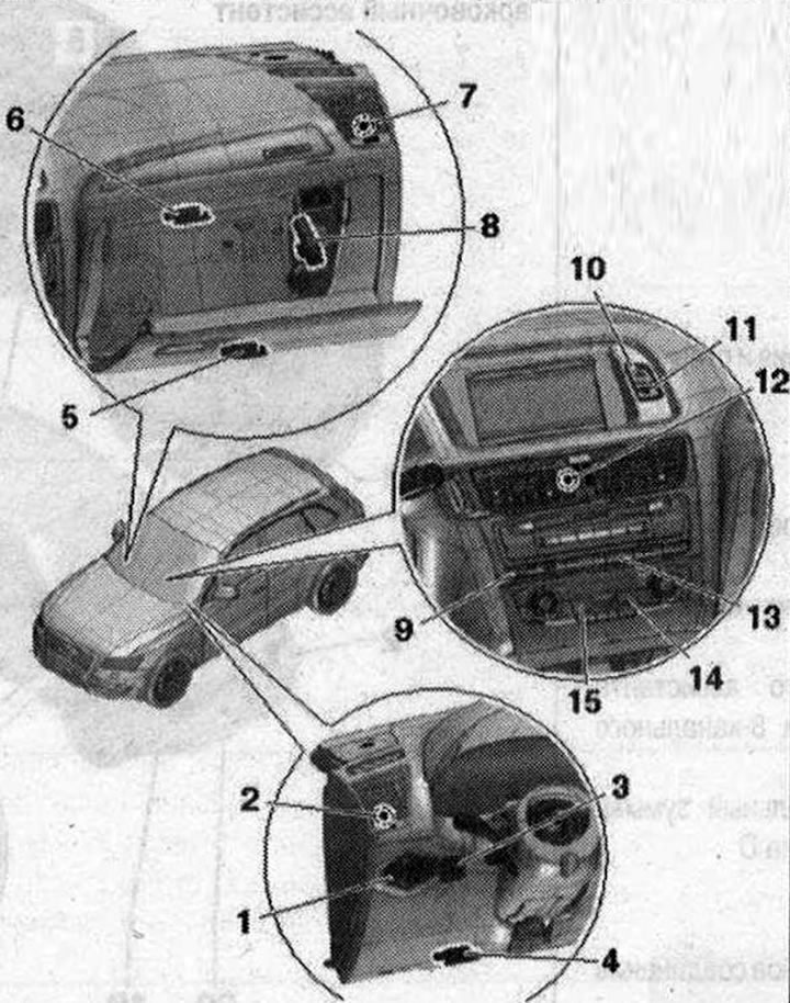
Lamps and switches on the front panel of the installation 1. Lighting control switch "E1" with switch and instrument panel lighting regulator "E20". With rear fog light switch "E314", fog light switch "E315"; 2. Left deflector illumination lamp on the front panel "L67"; 3. Headlight corrector regulator "E102"; 4. Front left footwell light "L151"; 5. Front right footwell light "L152"; 6. Glove box light "W6". 12V, 5W; 7. Right deflector illumination lamp on the front panel "L69"; 8. Glove box light switch "E26"; 9. Switch block for Charisma "E592" (only with set MMi-Comfort); 10. Hazard warning light switch "E229"; 11. Front passenger airbag deactivation indicator lamp "K145"; 12. Center illumination lamp, front panel deflector "L68". Built into the middle deflector of the front panel. In case of malfunction, the center deflector on the front panel cannot be replaced separately; 13. Keyboard (only with set MMi-Comfort). Depending on the kit, with rear window curtain switch "E149", button for ASR and ESP "E256", button for parking assistant "E266"; 14. Front passenger seat regulator with heating "E95". Integrated into the Climatronic control unit "J255" (also designated as "control and display panel"). Cannot be replaced separately if faulty; 15. Driver's seat regulator with heating "E94". Built into the Climatronic control unit "J255" (also designated as "control and display panel"). Cannot be replaced separately if faulty
Removal the left and right deflector illumination lamp on the front panel "L67" / "L69"
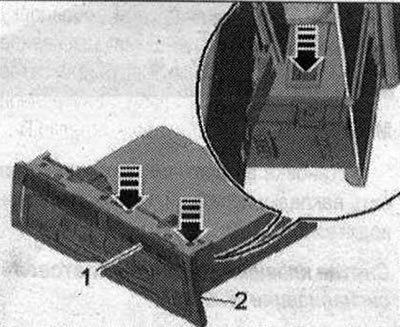
Switch off ignition. Remove the corresponding front panel deflectors. Unlock the clamps and disconnect the connector "1" on the front panel deflector. Carefully lift up the housing "2" for the LED with a small "arrow" screwdriver.
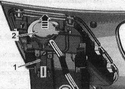
Remove the LED indicators for the front panel vents.
Installation
Installation in reverse order: install the front panel deflectors.
Removal the switch and instrument panel backlight regulator "E20"
The switch and instrument panel illumination regulator "E20" is located in a common housing with the light switch "E1" and cannot be replaced separately if a defect occurs.
Removal the rear fog light switch "E314", fog light switch "E315"
The rear fog light switch "E314" and the fog light switch "E315" are located in a common housing with the light switch "E1" and cannot be replaced separately if a defect occurs.
Removal the light switch "E1"
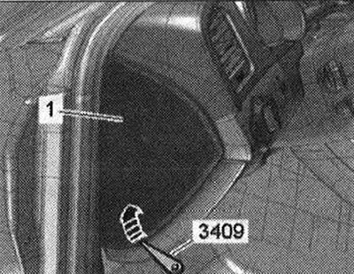
Turn off the ignition. Set the light switch to position "0". Lift the side trim "1" of the front panel with wedge "3409" "arrow" and remove.
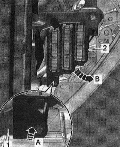
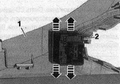
Unlock the clamp "arrow A" and remove the fuse block C -SC "pos. 2" in the direction of arrow B- on the central pipe "1" for the front panel and place it below.
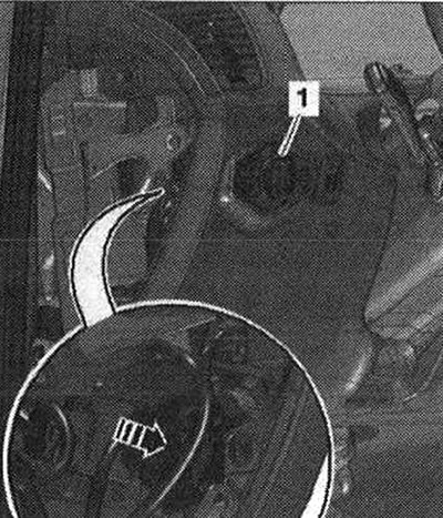
Reach through the side opening in the front panel and push the light switch "E1" "pos. 1" back out of the front panel trim on the driver's side "arrow". Disconnect the electrical plug connection.
Installation
Installation in reverse order: press the switch until the latch snaps into place in the switch housing.
Removal the headlight corrector regulator "E102"
Switch off the ignition. Remove the front panel trim on the driver's side. Carefully unlock the "arrow" latches with a small screwdriver. Squeeze the headlight corrector regulator -E102 "pos. 2" out of the bumper trim.
Installation
Installation in reverse order: install the front panel trim on the driver's side.
Removal the hazard warning light switch "E229"
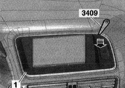
Switch off ignition. Lift cover "1" of MMI-interface screen with wedge "3409" at corners "arrow" and remove. Disconnect connector and remove cover of MMI-interface screen.
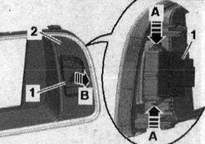
Unlock the clamps "arrow A" and press the hazard warning light button -E229 "POS. 1" out of the cover "2" of the MMI screen "arrow B".
Installation
Installation in reverse order: Press the cover for the MMI interface screen until the clips are fully engaged in the mounting points.
Removal the front passenger Airbag shutdown indicator lamp "K145"
The front passenger airbag deactivation indicator lamp "K145" is located in the same housing as the hazard warning light switch "E229" and cannot be replaced separately if a defect occurs.
Remove and install the keyboard in the front panel. Cars with MMI-Comfort package
Turn off ignition. Remove CD changer "R41". Carefully unlock the "arrow" latches with a small screwdriver. Press keyboard "1" out of the switch mounting socket "2".
Installation
Installation in reverse order: insert the key block into the switch housing until the lock engages with a clear click. Install the CD changer "R41".
Removal the front seat heating regulator "E94" / "E95"
The front seat heating controls are integrated into the Climatronic control unit "J255" (also referred to as "control and display panel"). They cannot be replaced individually.
Removal the glove box light "W6"
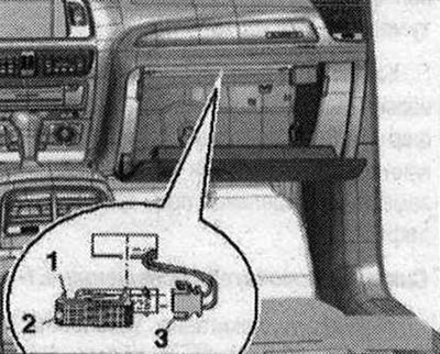
Switch off the ignition. Set the light switch to the "O" position. Press in the locking lug "1" with a flat screwdriver and remove the glove compartment light "2" by prying it off with a lever. Disconnect the electrical plug connection "3".
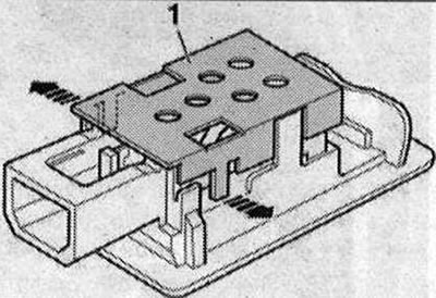
To replace the lamp, loosen the fastening brackets "arrows" and remove the cover "1" above the lamp.
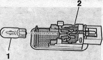
Remove lamp "1" on the back of the glove box light from socket "2".
Installation
Installation in reverse order: connect the plug connector. Insert the glove compartment light into the opening and fix it on the opposite side.
Removal the glove box light switch "E26"
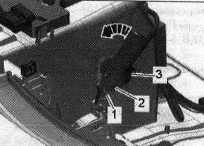
Switch off the ignition. Remove the glove box. Disconnect the electrical plug connection "3". Remove the hinge bolt "1". Unlock the switch "2" by turning it counterclockwise "arrow" and remove it.
Installation
Installation in reverse order: install the glove box.
Removal the front footwell light "L151" / "L152"
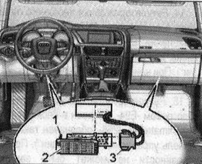
Switch off the ignition. Press in the locking tab "1" with a flat-head screwdriver and remove the footwell light "2" by prying it off with a lever. Disconnect the electrical plug connection "3".
Installation
Installation in reverse order: If the LED is faulty, replace the footwell light assembly. Insert the footwell light into the hole and fix it on the opposite side.