



Table of contents: Door trim - removal ↓ Front doors without switches on the… ↓ Cars with six-cylinder engines, as… ↓ All models ↓ Door Outer Part - Replacement ↓ Door lock - removal ↓ External Lock Handle - Removal ↓ Rotary switch of the lock on the… ↓ Window lifters - removal ↓ Door glass - replacement ↓
A special feature of AUDI 80 cars is their two-piece doors. The inner part, where the door elements are attached, is connected to the outer part of the door with four bolts. In the event of an accident with damage to the door, its outer part can be replaced without wasting time on the laborious process of attaching and adjusting the window lifter and lock mechanism.
Door seals require special care because cracks in the seals not only impair the tightness of the door, but also increase the noise of the flow around it while driving. The best way to care for the seals is deer fat. Its only drawback is that it prevents the seal from freezing to the body in the cold season.
To remove the doors where the speakers and electric windows are installed, you need to remove the door trim to disconnect their plugs. The same applies to the wires and hoses of the central lock.
1. Remove two hex bolts securing the lower and upper hinges on the door.
2. Remove the door. The hinges remain on the body.
3. Fit the newly installed door.
For correct door fitting, the car must stand horizontally on its wheels. If the door fitting is performed on a car placed on trestles, the fitting will be performed incorrectly due to the compression of the body under its own weight.
The gap between the attached parts at the front and back should be 56.5 mm. Otherwise, the door must be centered. The door must also match the contour of the body and should not protrude or sink.
The upper front edge of the rear side doors overlaps the middle roof pillar by 14.5 mm. This distance is measured and checked with the door closed. Based on this distance, the other edges of the door are adjusted. The front edge of the front door should be 0.5-1 mm inward from the edge of the front wing. The same applies to the next gap. The rear edge of the front door should protrude outward by 0.5-1 mm relative to the front edge of the rear side door. Accordingly, the rear edge of the rear side door should protrude the same distance relative to the rear wing.
4. To adjust the door longitudinally, unscrew the rear bolt securing the door hinge to the body, as well as the threaded sleeve located underneath it.
5. Loosen the front door hinge bolt to the body so that the door can be moved (see illustration).
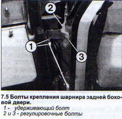
6. Close the door and level the gap.
7. Carefully open the door and tighten the loosened front bolt securing the door hinge to the body.
8. Screw in the threaded sleeve and tighten the rear bolt securing the door hinge to the body.
9. Loosen the bolts securing the door hinges to the body and move the door down or up if necessary to adjust the door height.
10. Tighten the loosened hinge bolts.
11. Loosen the bolts securing the door hinge to the door if adjustment of the door front edge is necessary.
12. Close the door and adjust the door gap.
13. Open the door and tighten the hinge bolts.
14. Loosen the door lock pin if necessary to adjust the position of the door rear edge (see illustration).
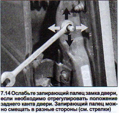
15. Close the door and adjust the door gap.
16. Open the door and tighten the door lock pin.
17. Check from inside the passenger compartment that the door seal is evenly seated in the opening.
18. Align the frame in the glass opening in the door. This adjustment is necessary if the door "casing" was not correctly placed on the inside.
19. Remove the door trim and loosen the four connecting bolts if necessary to align the opening.
20. Close the door.
21. Ask an assistant to insert the frame into the opening. It is better to push the frame deeper, because the sealing rubber will push it back.
22. Tighten the connecting bolts. First tighten the upper ones, then the lower ones. Tightening torque 20 Nm.
Door trim - removal
The procedure for removing door trim is shown using the front doors as an example. The trim on the other doors is removed in an identical manner.
23. Disconnect the window lift handle. To do this, insert a screwdriver into the hole between the handle and the handle axle cover and press the lock (see illustration).
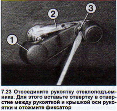
24. Remove the handle axle cover.
25. Remove the Phillips head screw located under the cover.
26. Remove the switches (see the relevant chapter).
Front doors without switches on the armrest
27. Remove the two screws securing the lower part of the armrest trim and remove it. There are two screws underneath that hold the upper part of the armrest trim (see illustration).
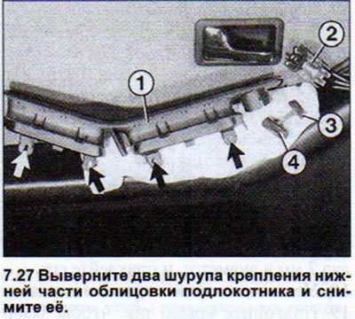
Underneath it are two screws holding the upper part of the armrest trim 1. 2 — the mechanism for adjusting the outside rear-view mirrors. 3 and 4 — the handles for adjusting the outside mirrors. Cars with four- and five-cylinder engines, as well as with diesel engines
28. Remove these screws.
29. Remove the handle for mechanical adjustment of the outside rearview mirrors. Use a screwdriver if necessary.
30. Push the armrest towards the rear edge of the door to release the front part from the mount. This requires a lot of force.
31. Lift the armrest up.
32. Release the mirror adjustment mechanism from the retaining clips on the armrest.
Cars with six-cylinder engines, as well as diesel engines, produced since 7/93.
33. Remove the three 4mm socket head screws on the underside of the armrest (see illustration).
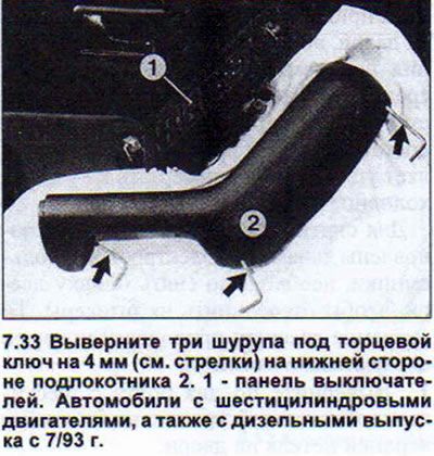
34. Remove the armrest, disconnect the plug and remove the switch panel.(see illustration 7.33).
35. Detach the armrest holder.
All models
36. Pull the inside door handle towards you.
37. Remove the Phillips head screw that secures the interior handle trim. The screw is located underneath the door handle.
38. Move the handle trim forward and remove it.
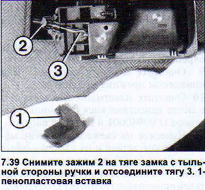
39. Remove the tension clamp from the crutch side of the handle and disconnect the rod (see illustration).
40. Remove the two screws securing the trim at the top of the door.
41. Disconnect the door glass opening sealing rubbers covering the door trim.
42. Remove the door trim by hitting it with your palm to release it from its mountings (see illustration).
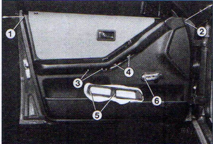
7.42 Remove the indicated screws and remove the door trim.
1 and 2 - upper side screws
3 and 4 - screws for fastening the upper armrest cover
5 - screws for fastening the lower part of the armrest
6 - window lift handle
Before installing the door trim, secure the rubber inserts. To make them go in easier, lubricate them with Vaseline or silicone paste.
43. Make sure that the lock release button fits exactly into the hole in the upholstery.
Door Outer Part - Replacement
If the outer part of the door is damaged, it must be replaced. We recommend varnishing the new outer part of the door before installation.
44. Remove the door trim.
45. Remove the door and place it on a soft surface with the outside facing up (foam, wool blanket).
46. Disconnect the lock leash from the inner lock handle rod.
47. Remove the four connecting bolts that hold the door "casing" and its inner part together (see illustration).
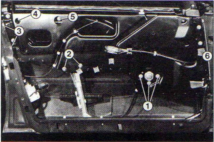
7.47 Door with trim removed
1 - window lift mechanism bolts
2, 5 - window lift guide bolts
3, 6 - connecting bolts of the outer and inner parts of the door
4 - door armrest mounting bolt.
Door lock - removal
48. Remove the two 6mm socket head screws.
49. Move the lock back a little. This will provide access to the lock leashes (see illustration).
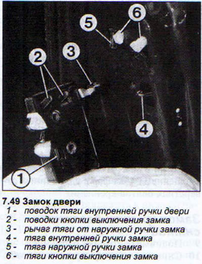
50. Disconnect the rods from the inner lock handle and from the lock switch button.
51. Turn the lock 90° to provide access to the rods from the outside handle.
52. Remove the interior door trim to provide easy access to the lock components during installation.
53. To secure the rod from the inner handle to the lock leash, move the leash over the lock with a screwdriver and hold it while securing the rod.
External Lock Handle - Removal
54. Remove the door trim.
55. Unscrew the bolt with a T25 socket head in the door opening, acting from its inside (see illustration).
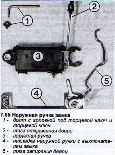
Approximately at the level of the door lock, in its cavity, there is a locking lever. Put your hand into the cavity of the door and turn the leash approximately 65° in the opposite direction from the lock.
Now the handle can be removed by pulling it inward. Remove the lock switch and cover plate by pushing it outward. Turn the cover plate slightly.
56. Disconnect the lock drive cable.
Rotary switch of the lock on the outside handle - removal
57. Remove the outer handle.
58. Insert the key into the switch to prevent the cylinders and springs from falling out when the switch is removed.
59. Remove the retaining ring from the rear end of the switch.
60. Remove the lock drive pin and spring. Before doing this, mark their position to facilitate subsequent assembly.
61. Remove the rotary switch from the trim.
62. Apply a protective lubricant to the new rotary switch before installing it to prevent rust.
Window lifters - removal
63. Remove the door trim.
64. Remove the four connecting bolts that hold the inner and outer parts of the door together and remove the inner part. The outer part remains hanging on the hinges.
65. Remove the retaining ring securing the glass to the window regulator. Remove the glass.
66. Unscrew the bolts securing the window lift mechanism. For electric window lifters, you need to unscrew the nuts instead of the bolts. The window lifters and their mechanism (for electric window lifters, the electric motor) are a single unit and must be removed or replaced as a set.
Door glass - replacement
67. Remove the window lifters.
68. Remove the glass seals on the guides.
69. Reinstall the seals after installing the glass. The distance from the bottom edge of the gasket to the bottom edge of the guide should be 25 mm.
(The original publication in its entirety is posted on the website «AUDIMANUAL.RU»)