



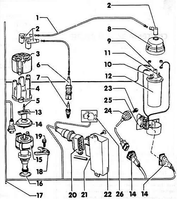
1 - ignition wire
2 - Radio interference suppression plug
3 - shielding ring
4 - distributor cap
5 - distributor cap corner with spring
6 - spark plug tips
7 - spark plug, 20 Nm
8 - lid
9 - terminal 4
10 - terminal 1 (-)
11 - terminal 15 (+)
12 - ignition coil
13 - distributor runner
14 - connection plug
15 - ignition distributor
16 - gasket
17 - bus for VEZ, KE-Jetronic
18 - terminal
19 - mounting bolt, 25 Nm
20 - connection plug
21 - connection nipple. For vacuum lines from the throttle body. Only available for engines with the designation "PS"
22 - control unit - VEZ. Behind the trim in the footwell, front right
23 - bolt.
Note: Tightening torque is important for the operation of the knock sensor. Tightening torque for M6 thread: 10 Nm; for M8: 13 Nm.
24 - knock sensor. On the engine block
25 - final stage
26 - Engine electronics control lamp
The VEZ electronic system is a transistor ignition system with an electronic control device. The control device is used to form an ignition signal in the field of a number of parameters. In the TSZ system, the ignition timing is adjusted by mechanical and vacuum regulators.
In an electronically controlled ignition system, the optimum ignition timing is determined based on the current operating conditions of the vehicle. The initial parameters are engine speed, engine temperature and engine load (suction pressure, throttle position). These parameters characterize the state of the engine at the moment. At the same engine speed, (let's assume 4000 rpm.) there is a difference when driving a car uphill or downhill.
The required performance of the engine ignition system is determined during engine testing on a stand, and is further specified during test driving of the car. The optimal performance ensures optimal fuel consumption, exhaust gas composition and driving performance.
During driving, the control unit receives information from sensors about the engine speed and its load. Based on the ignition system characteristic available in the control unit, the control unit determines the optimal ignition timing, for example, in the range from 10° to 0°, before TDC.
In addition to the above parameters, the detonation sensor data also influences the ignition timing. Since fuel consumption decreases with increasing compression ratio, modern engines strive to increase the compression ratio. However, this can lead to an uncontrolled combustion process of the mixture, which leads to detonation phenomena.
Over time, detonation knocks can lead to engine damage. To avoid this, a detonation sensor is needed. Its task is to determine the occurrence of detonation, which is a prerequisite for measuring the ignition timing in the direction of delay. The detonation sensor is located on the cylinder block and is connected by an electrical conductor to the ignition control unit. If the sensors that inform the control unit about the engine condition fail, this can negatively affect its operation, causing a decrease in engine power and an increase in fuel consumption. However, this will not cause serious damage to the engine if the malfunction is quickly eliminated.
Information obtained from this resource: AUDIMANUAL