The Audi 80/90 cars are driven by in-line water-cooled engines located in the engine compartment along the car.
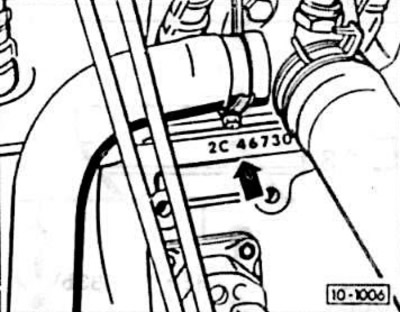
Depending on the engine, the car is equipped with a carburetor or an electronic fuel injection system and, therefore, a corresponding ignition system. This information can be found in the table below. The identification number of the car, stamped on the left side of the engine block (arrow) and the data in the table can be used to identify your car.
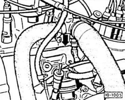
The figure shows a 4-cylinder carburetor engine.
For new models, the engine designation may consist of one number and one letter, while for earlier models it may consist of two letters.
Attention! The material presented in this manual is primarily aimed at operating the vehicle in the CIS countries.
The description of the repair is made in a simple, understandable form for everyone. If you follow the text and pictures step by step during the repair, then there should be no difficulties.
Such simple techniques as, for example, "open the engine hood" when working in the engine compartment or "unscrew the pump nut" when working with the wheel brake system are not always mentioned. At the same time, difficult work is described in detail.
The following chapter provides repair specifications for vehicles, which are an important and integral part of this Manual.
Attention: They must be followed for any type of repair work.
Attention: Repair parameters should be read specifically for the required model to avoid possible errors.
For ease of use, electrical circuits are presented in the relevant sections of the proposed material.
In a passenger car for power supply of all consumers (headlights, radios, etc.) up to 1000 m of wires were laid.
If you need to troubleshoot a problem or want to install additional equipment, you cannot do without an electrical diagram; it shows current circuits and wire connections. The current circuit must be closed, otherwise no current will flow through it. For example, it is not enough to connect voltage to a headlight without connecting its circuit to ground.
Therefore, the ground wire connects the battery to the body. Sometimes this connection to the ground is not enough and the ground is supplied to the consumer by a separate wire, usually in brown insulation. Switches, fuses, measuring devices, electric motors and other electrical elements are included in separate circuit currents. For correct connection, their contacts have corresponding designations.
To organize the wires in the diagram, individual current circuits are placed next to each other and numbered.
The vertical lines approach the field, most often highlighted in gray. This field shows the relay board with holders and through them it is connected to the positive supply of the current circuit. In any case, the relay board also has an internal ground wire (terminal 31). The thin lines in this field represent the internal connections of the individual current circuits on the relay board. At the bottom, each current circuit is connected to a horizontal line, which represents the connection to ground. The connection to ground is usually made through the body or by a separate wire from the ground connection point located on the body.
If a current circuit is interrupted by a square with a number inside, then this number indicates the current circuit in which this current circuit continues.
The most reasonable way to use electrical diagrams is as follows:
First, you need to find the desired element in the list of designations, for example, the heater fan switch. In the right column next to the name of the element, the current circuit number is indicated, which is also shown in the diagram on the lower horizontal line.
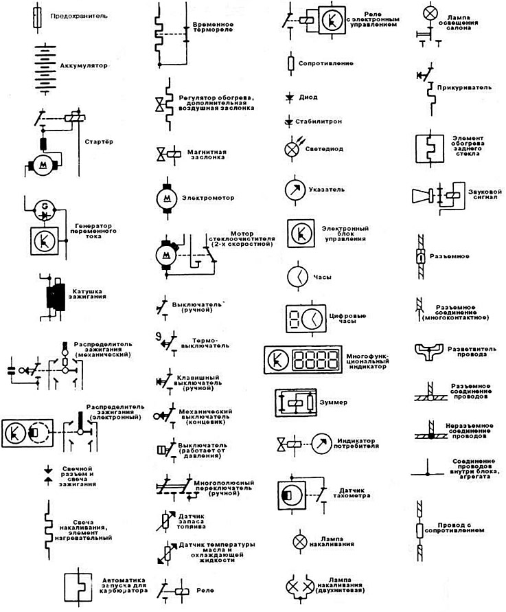
To be able to read an electrical diagram, it is necessary to know the meaning of the symbols of some elements, in addition, you should know the most important switching symbols.
Designations of the most important elements:
| Designation | Element |
| A | Battery |
| IN | Starter |
| WITH | Alternator |
| D | Ignition switch |
| E | Manually operated switch |
| F | Mechanical switch |
| G | Sensor, control device |
| N | Sound signal |
| Dual tone sound signal, fanfare | |
| J | Relay, control unit |
| K, L, M, W, X | Control lamps, lamps, illuminators |
| N | Electrovalves, resistors, switching units |
| ABOUT | Distributor |
| P, Q | Spark plug connector, spark plugs |
| ignition | |
| R | Radio |
| S | Fuses |
| T | Detachable connections |
| V | Electric motors |
To accurately determine the letter of the symbol, the ordinal number of the element is given.
Relays and electronic control units are usually depicted on a gray background. The lines depicted there are internal connections. They show how switching occurs inside the relay or electronic or electrical elements or how they are connected to each other on the relay board.
The number in the black square represents the relay on the relay board with fuse holders. Directly next to the relay shown is the contact designation.
Example: If a contact on the diagram is labeled 17/87, this means that 17 is the terminal number on the relay board, and 87 is the terminal designation on the relay or on the control unit.
The terminals in the diagrams are designated in accordance with DIN standards. The most important terminals are designated as follows:
Terminal 30. Battery voltage is always applied to this terminal. The wire is always red or red with colored stripes.
Terminal 31 connected to ground. Ground wires are usually brown.
Terminal 15 is fed through the ignition switch. Voltage is present when the ignition is on. The wires are usually green or green with colored stripes.
Terminal X is also energized when the ignition is on, but the voltage is removed when the starter is turned on. This ensures that the entire battery power is supplied to the ignition system when the engine is started. All more or less powerful consumers are powered from this terminal. The high beam is also turned on from this terminal. Thus, when the ignition is turned off, the high beam is automatically switched to the sidelights. In the electrical diagram, individual wires are designated by numbers and letter combinations below the numbers.
Example: 1.5 ws/ge
The numbers indicate the cross-section of the wire. The letters indicate the color of the wire. If the designation has two groups of letters separated by a fraction, as in the example given, the first group of letters indicates the main color of the wire: ws=white, and the second additional color: ge=yellow. If it happens that wires of the same color are used in different current circuits, it is recommended to check the color combinations at the corresponding connection point. White wires have a number for differentiation, which is indicated on the diagram under the color designation.
Conventional designations of wire colors:
- bl = blue
- br = brown
- ge = yellow
- gn = green
- gr = gray
- rt = red
- sw = black
- li = purple
- ws = white
Wires connected by single- or multi-pin connectors have a digital combination in addition to the connector designation "T". Example: T2p = two-pin connector, T32/27 = 32-pin connector with 27 contacts used.
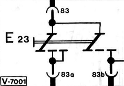
In the electrical diagrams, all consumers and switches are shown in the off state. Switching of the current circuit by a switch is shown here using the example of a two-position switch.
When switching the switch E23 to the first position, the current will flow from terminal 83 through terminal 83a. The second voltage of the switch is not connected in this position. Only when switching the switch to the second position, the current will flow from terminal 83 through terminal 83b. In this case, the connection of terminal 83 with terminal 83a is maintained.
Conventional symbols of elements in electrical circuits