
Note: All switches and contacts are shown in a mechanically at rest state.
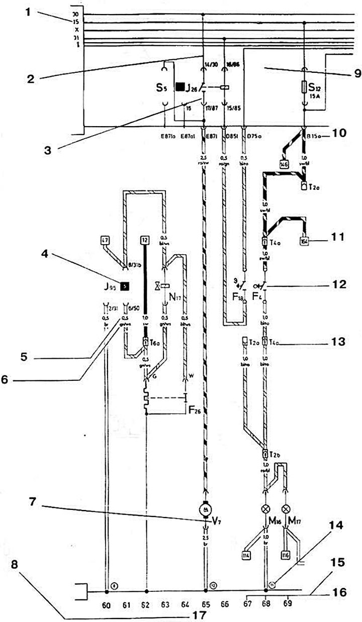
1 - Terminal designation 15 - battery voltage is supplied when the ignition is on.
2 - Internal connections (thin lines) These connections are not made by external wires, but by conductive connections inside the blocks.
3 - Contact designations on the relay/control unit and on the relay board/additional relay box - e.g. 17/87 = on the relay board.
4 - Relay pad number indicates the number of the relay pad on the relay board or on the additional relay unit
5 - Wire cross-section in mm.
6 - The color of the wire matches the color of the wire in the car. Here: green white.
7 - Designation of a group of elements. With its help, you can find out from the legend what the symbol on the diagram means. Here - a radiator fan.
8 - Designation of the element whose image is present in the current circuit
9 - This field represents the relay board with fuse holders.
10 - Alphanumeric combination next to the connector contacts, shows the connection of the wire in a multi- or single-contact connector. For example. B 15a - multi-contact connector B. contact 15a.
11 - The numbers in the square show the interruption of the wire and provide a reference to the current loop where the continuation follows.
12 - Switch symbol. This is the switch for the reversing lights.
13 - Alphanumeric combination means plug connection. Here T4 is a 4 - pin connector. Designation T14/12 means T14 is a 14 - pin connector. 12 = contact 12.
14 - The numbers in the circle indicate the location or position of the ground connection point (see legend).
15 - Vehicle weight.
16 - Current circuit number to facilitate the location of elements on the electrical diagram (see legend).
(The original material is located on the website audimanual)