
Table of contents: Removal ↓ Installation ↓
To turn the wheels, constant velocity ball joints (CV joints) are located on the drive shafts (half-axles). The drive of each wheel consists of two constant velocity joints and a shaft. The drive shafts of the front wheels are equipped with two types of joints. The outer CV joint is a ball bearing joint, and the inner one is designated "Tripod". Instead of six balls, "Tripod" joints have three rollers on needle bearings (see illustration 6.0). The CV joints of the rear wheel drive shafts are ball bearing (see illustration 6.0a).
Constant velocity joints are protected from moisture and dust by covers (anthers), the condition of which must be checked regularly. Damaged or cracked covers should be replaced immediately, because moisture and dust will destroy the CV joint.
Attention! Do not move the vehicle after removing the drive shaft. This may cause damage to the hub bearing due to the lack of axial load. If it is necessary to move the vehicle, you can install the outer CV joint tailstock in the hub instead of the drive shaft and secure it with an M14 or M16 bolt with a tightening torque of 115 or 190 Nm.
Removal
Attention! The procedure for removing and installing the drive shaft is shown using the front axle shaft as an example.
1. Loosen the bolt securing the drive shaft end to the hub (see illustration 6.0).
Attention! When unscrewing the hub bolt, the car must stand on its wheels.
2. Mark with paint the position of the front wheel on the hub whose drive shaft will be removed. This will allow the balanced wheel to be installed in its original position during assembly.
3. Loosen the wheel mounting bolts.
4. Jack up the front of the car, place it on jack stands and, after unscrewing the mounting bolts, remove the wheel.
5. Completely unscrew the drive shaft mounting bolt in the hub.
6. Unscrew the bolts that secure the inner CV joint 1 to the gearbox (see arrows in the illustration).
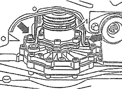
6.6. Unscrew the bolts that secure the inner CV joint 1 to the gearbox (see arrows)
7. Release the ABS sensor wire from the holder, unscrew the mounting bolt and disconnect the ABS sensor from the steering knuckle
8. Disconnect both upper arms from the steering knuckle by unscrewing the tie bolt.
9. Move the steering knuckle to the side, remove the outer CV joint tail from the hub and remove the drive shaft.
Installation
10. Secure the drive shaft to the gearbox and into the hub.
11. Tighten the drive shaft to gearbox mounting bolts in a crisscross pattern. Bolt tightening torques:
- m8 bolts - 40 Nm;
- m10 bolts - 70 Nm.
12. Pull the drive shaft end into the hub by screwing in and tightening the new hub bolt. The final tightening of the hub bolt is done after the vehicle is installed on the wheels.
13. Install both upper arms onto the steering knuckle, pressing the pins of their ball joints into the corresponding holes, and tighten the tie bolt.
14. Install the ABS sensor on the steering knuckle in its original position, and secure its wire in the holder on the caliper.
15. Lower the car onto its wheels and tighten the drive shaft end mounting bolt in the hub. Ask an assistant to depress the brake pedal and hold it in this position. Tighten the M14 bolt with 115 Nm. If the drive shaft is mounted in the hub with an M16 bolt, then tighten it at this stage with 190 Nm. Then tighten the bolt with a wrench by 180°.
16. Install the front wheel on the hub so that the marks made before removal match. Before installing the wheel, lubricate the seat of the wheel disk on the hub with a thin layer of bearing grease. Do not lubricate the wheel bolts. Replace rusted wheel bolts with new ones and screw them in.
17. Tighten the wheel bolts in a cross pattern to 120 Nm.
Attention! If the CV joint has been overhauled, grease is packed into the CV joint and its boot during assembly.
Table of lubricant filling in CV joints
| CV joint | outer | outer | ||
| Tripod | interior | interior | ||
| CV joint diameter | 88 mm | 98 mm | 100 mm | - |
| AUDI Lubricant | G 000 603 | G 000 633 | G 000 605 | G 000 605 |
| Total volume | 90 g | 120 g | 120 g | 130 g |
| CV joint grease volume | 40 g | 80 g | 70 g | 70 g |
| Volume of grease in the cuff | 50 g | 40 g | 50 g | 60 g |