
Attention! The hood is made of aluminum. For this reason, threaded connections should be made only with appropriate bolts, nuts, gaskets, etc. Otherwise, corrosion may occur at the points of attachment with unintended elements. The connecting elements have a special coating, which can be recognized by a greenish tint.
Removal
1. Open the hood and disconnect the washer fluid supply hose and the nozzle heater plug. Release the washer hose from the mount.
2. Mark the position of the hood by tracing the places where the nuts of the 4 hood hinges fit with a felt-tip pen or marker (see illustration 8.0).
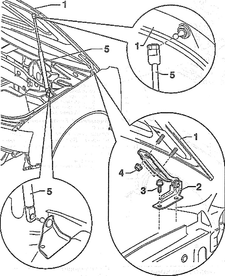
8.0. Hood and its fastening:
1 - hood
2 - loop
3 - bolt with a multi-sided head
4 - hexagonal nut. Tightening torque 15 Nm
5 - gas-filled bonnet strut
3. Ask an assistant to hold the hood.
4. Remove the upper support 1 of the gas-filled strut 5 of the hood from the ball joint by pressing the retainer with a small screwdriver (see arrow in illustration).
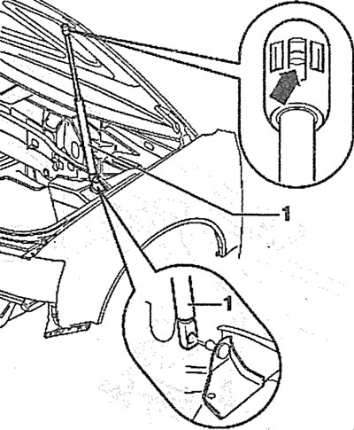
8.4. Remove the upper support 1 of the gas-filled strut 5 of the hood from the ball joint by pressing the retainer with a small screwdriver (see arrow)
5. Remove the lower support of the stop in the same way.
6. Unscrew nuts 4 and remove the hood, working together with an assistant (see illustration 8.0).
Installation
7. Restore the paintwork of the hood, if necessary.
8. Install the hood in place, working together with an assistant. Fit the hood, using the marks on the hood hinges made before dismantling. If a new hood is installed, its position will need to be adjusted.
9. Install the gas-filled bonnet strut, observing the correct installation position. The strut rod must be facing upwards.
If the hood adjusting buffers were removed, their height will need to be adjusted. To do this, screw the buffers into the seat until they stop. After that, unscrew the buffers back until the hood is level with the wings when closed.
10. Connect the hose for supplying the washing liquid and the plug of the nozzle heater to the jet. Secure the hose and wire in the holders on the hood.
Fitting the hood
11. Loosen nuts 4 (see illustration 8.0), so that the hood can be moved in the longitudinal and transverse directions
12. Close the hood and center it between the fenders, ensuring that the gap between the edges of the hood and the adjacent front parts is parallel (see illustration).
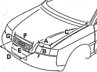
8.12. Bonnet gaps:
A - 5.0 mm + 1 mm
B - 5.0 mm + 1 mm
C - 3.0 mm + 1 mm
D - 5.0 mm + 1 mm
E - 2.0 mm±0.2 mm
F - 2.0 mm±0.2 mm
G - 2.5 mm±0.2 mm
13. Carefully open the fitted bonnet, without allowing it to move, and tighten the hinge nuts with a force of 15 Nm.
14. Slightly loosen the four bolts 2 that secure the hood lock 1 (see illustration).
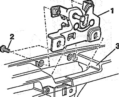
8.14. Slightly loosen the four bolts 2 that secure the hood lock 1
15. Adjust the position of the hood relative to the adjacent front parts by moving the lock.
16. Tighten the lock mounting bolts to 10 Nm.
17. Adjust the hood height relative to the fenders. To do this, screw stop buffers 1 and 2 into the hood. Unscrew the buffers one by one to achieve the desired position of the hood relative to the fenders. Place putty or plasticine on the buffer contact area to determine whether the buffer contacts the upper front cross member when the hood is closed (see illustration).
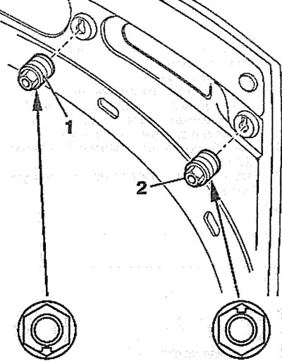
8.17. Screw the stop buffers 1 and 2 into the hood