
Table of contents: Removal ↓ Installation ↓
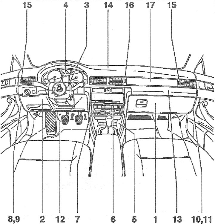
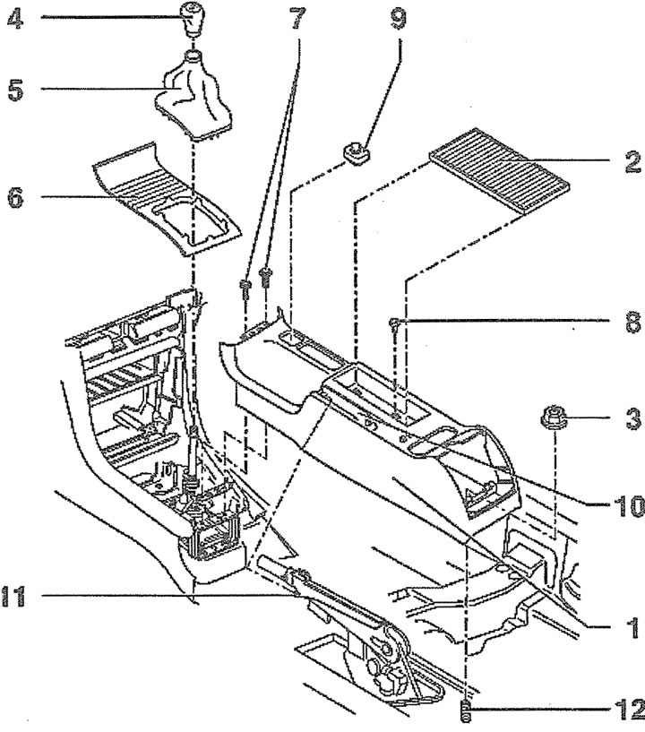
16.0. Main elements of the instrument panel:
1 - storage box
2 - pocket on the driver's side
3 - steering column switches
4 - instrument panel
5 - front part of the central console
6 - radio/heater/air conditioning switch unit
7 - Instrument panel bracket
8 - left side cover of the instrument panel
9 - bolts for fastening the left side panel
10 - right side cover of the instrument panel
11 - bolts for fastening the right side panel
12 - Instrument panel mounting bolts on the driver's side
13 - Front passenger airbag
14 - photocell
15 - plugs for the illumination of the side deflectors and the air temperature sensor
16 - plug for illumination of central deflectors control
17 - adjustment
Removal
1. Disconnect the negative (-) battery terminal, remove the steering wheel airbag and the steering wheel.
2. Remove the instrument panel, see the relevant chapter.
3. Release the left side cover of the instrument panel from the clips and remove it.
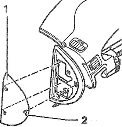
4. Remove the five screws 2 securing the pocket on the driver's side (see illustration).
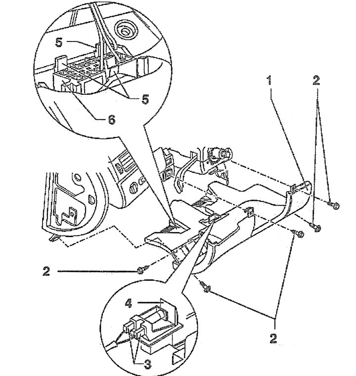
16.4. Pocket 1 on the driver's side and its fastening:
2 - mounting screws
3 - plugs
4-legroom lighting lantern
5 - clamps
6 - diagnostic connector
5. Move the pocket down, disconnect plugs 3 and 4 of the footwell light, release the self-diagnosis system plug 6 from the holder by squeezing the three leashes 5 (see illustration 16.4) and remove the pocket.
6. Open the glove compartment lid and unscrew the three screws 3 (see illustration).
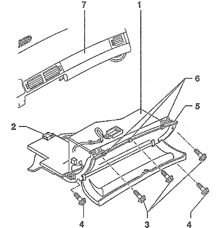
16.6. Open the glove compartment lid and unscrew the three screws 3:
5 - overlay
6 - rubber cushions
7 - instrument panel
7. Unscrew the two screws 4 and remove the glove box 1 by moving it downwards (see illustration 16.6).
8. Disconnect plug 2 of the glove compartment light (see illustration 16.6).
Caution! The front passenger airbag can be deactivated if necessary. When removing the glove compartment, you will need to disconnect the airbag deactivation sensor plug.
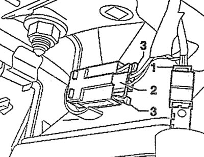
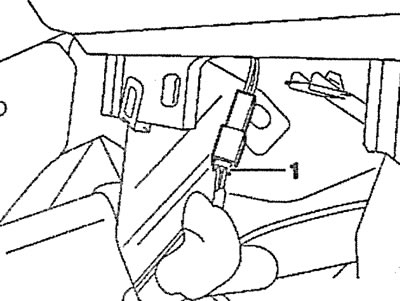
9. Press the leash 3 and disconnect the plug 2 of the airbag deactivation sensor from the switch 1 (see illustration).
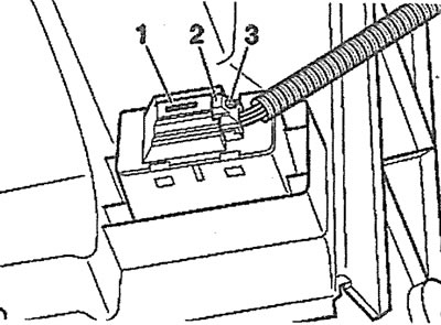
16.9. Press the leash 3 and disconnect the plug 2 of the airbag deactivation sensor from the switch 1
10. Remove the deflector 1 on the rear of the centre console using a suitable hook or a screwdriver bent at a 90° angle (see illustration).
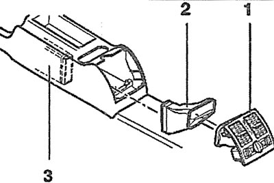
16.10. Remove the deflector 1 on the rear of the central console using a suitable hook or a screwdriver bent at an angle of 90°
11. Disconnect the plugs from the cigarette lighter, rear air vent lighting and rear seat heater.
12. Disconnect adapter 2 from air duct 3 (see illustration 16.10).
13. Remove the rear seat center armrest, if equipped.
14. Unscrew nut 3, remove cover 2 and unscrew screw 8 (see illustration).
16.14. Elements of the rear part of the central console:
1 - rear part of the center console
2 - lid
3 - nut. Tightening torque 10 Nm
4 - gear shift lever handle
5 - gear shift lever cover
6 - front console insert
7 - screws. Tightening torque 5 Nm
8 - screw. Tightening torque 5 Nm
9 - mirror position switch
10 - parking brake lever trim
11 - adjusting the parking brake lever
12 - hairpin
15. Cars with a manual transmission. Unscrew the ball head 4 from the gearshift lever and remove the protective cover 5, releasing it from the clips (see illustration 16.14).
16. Vehicles with automatic transmission. Remove insert 6 from the front of the center console by pushing it upwards (see illustration 16.14).
17. Unscrew two screws 7 (see illustration 16.14).
18. Remove the trim 11 of the parking brake lever (see illustration 16.14).
19. Lift the cover 1 of the center console upwards and disconnect the plug of the mirror position switch (see illustration 4.5).
20. Fully apply the parking brake.
21. Remove the lining 10 of the parking brake lock 11 (see illustration 16.14).
22. Remove the center console cover from stud 12 and from the parking brake lever (see illustration 16.14).
23. Remove the ashtray and release the cover 2 of the six fasteners 3, starting from the bottom if the car is not equipped with a navigator (see illustration).
16.23. Elements of the front part of the central console
1 - front part of the central console
2 - decorative overlay
3 - pad retainers
4 - pad retainers
5 - Switch panel cover
6 - screws. Tightening torque 5 Nm
7 - overlay
8 - nut
9 - mounting angle
24. Remove the radio and air conditioner/heater switch unit.
25. Remove the ashtray.
26. Remove the decorative cover 5 from the switch panel by releasing it from the four fasteners 4 (see illustration 16.23).
27. Unscrew four screws 6 (see illustration 16.23).
28. Remove cover 7 and unscrew nut 8 (see illustration 16.23).
29. Remove the center console by lifting it off the bolts on the driver's side and pushing it back.
30. Unscrew the six bolts 2, move the switch panel 1 into the passenger compartment, disconnect the plugs of the hazard warning light switch, glove compartment light and drink holder on the rear side of the panel and remove the panel by cutting the wire fastening clamps (see illustration).
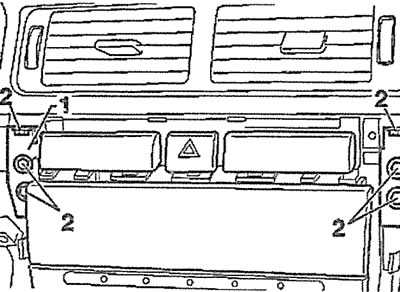
16.30. Unscrew the six bolts 2 and remove the switch panel 1 from the instrument panel
31. Unscrew the two bolts 1 and remove the steering column lock handle 2 by lowering the steering column all the way down (see illustration).

16.31. Unscrew the two bolts 1 and remove the steering column lock handle 2
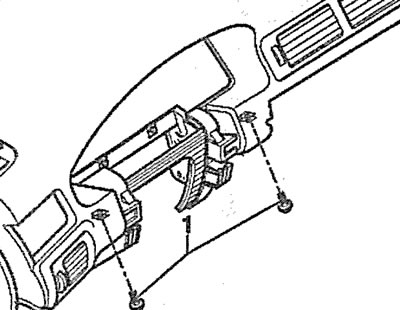
32. Unscrew the two bolts (see arrows in the illustration) steering column trim and remove the upper part 1 of the trim.
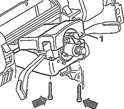
16.32. Unscrew the two bolts (see arrows) steering column trims and remove the upper part 1 of the trim
33. Unscrew two bolts 2, bolt 1 and remove the lower part 3 of the steering column trim (see illustration).
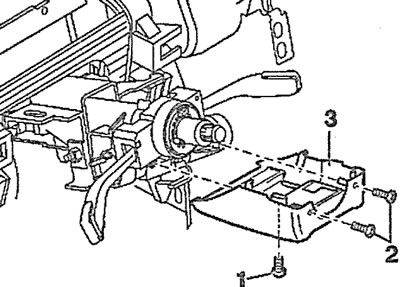
16.33. Unscrew two bolts 2, bolt 1 and remove the lower part 3 of the steering column trim
34. Disconnect plug 1 and remove the contact ring (loop) from the steering shaft by pressing the locking tabs (see arrows in the illustration).
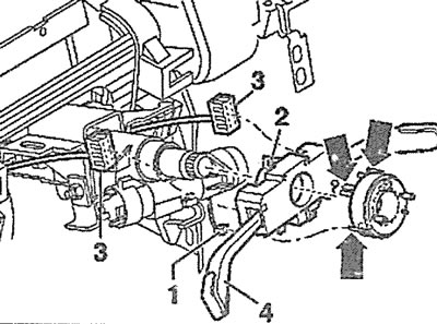
16.34. Disconnect plug 1 and remove the contact ring (loop) from the steering shaft by pressing the locking tabs (see arrows)
35. Unscrew bolt 2, disconnect two plugs 3 and remove steering column switch 4 (see illustration 16.34).
36. Unscrew the five bolts 1 and remove the support bracket 2 (see illustration).
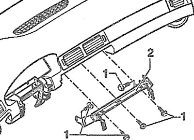
16.36. Unscrew the five bolts 1 and remove the support bracket 2
37. Use a screwdriver to pry off cover 1 from the left end of the instrument panel (see illustration).
16.37. Use a screwdriver to pry off cover 1 from the left end of the instrument panel
38. Unscrew the three bolts 1 and remove the cover from the right end of the instrument panel, prying it off with a screwdriver (see illustration).
16.38. Unscrew the three bolts 1 and remove the cover from the right end of the instrument panel
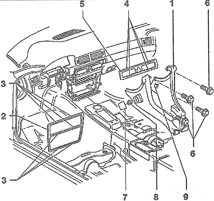
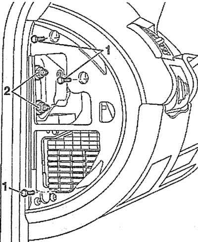
39. Unscrew the bolts securing the left side of the instrument panel (see illustration).
16.39. Unscrew bolts 1 and 2 securing the left side of the instrument panel
40. Unscrew the two bolts 1 that secure the instrument panel on the driver's side (see illustration).
16.40. Unscrew the two bolts 1 that secure the instrument panel on the driver's side
41. Disconnect connector 1 of the front passenger airbag by prying it with a screwdriver to remove it from the retaining tabs 2 and feed it in the direction of arrow 3 (see illustration).
16.41. Disconnect connector 1 of the front passenger airbag by prying it off with a screwdriver
42. Unscrew bolts 1 and remove the airbag (see illustration).
16.42. Unscrew bolts 1 and remove the airbag
43. Remove the photocell by carefully removing cover A, unscrewing bolt B and disconnecting the plug (see illustration).
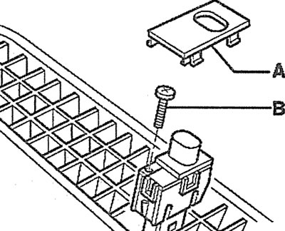
16.43. Remove the photocell by carefully removing cover A, unscrewing bolt B and disconnecting the plug
Attention! Secure the photocell plug with a string or clamp.
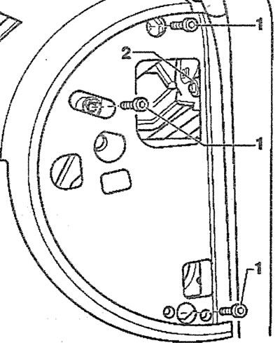
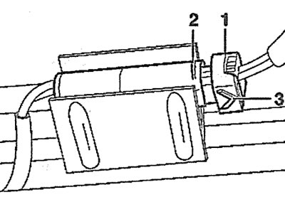
44. Disconnect the plugs 1 of the side vent control illumination on the right and left sides, as well as the plugs 2 of the air flow temperature, by pressing the leashes 3 (see illustration).
16.44. Disconnect plugs 1 of the side vent control illumination on the right and left sides, as well as plugs 2 of the air flow temperature
45. Disconnect plug 1 of the central air vent control illumination on the instrument panel (see illustration).
16.45. Disconnect plug 1 of the central vent control illumination on the instrument panel
46. Make sure that all components of the instrument panel fastening, as well as wires, are disconnected from it and remove the panel, moving it into the passenger compartment.
Installation
The installation of the instrument panel is carried out in the reverse order of its removal.
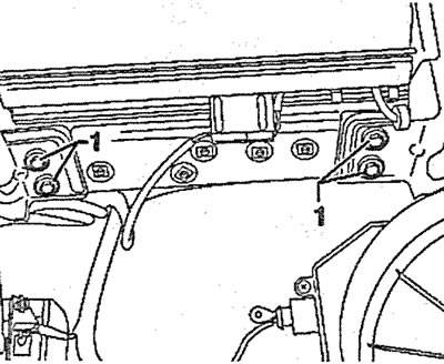
47. Before installing the panel, make sure that there are holders 1 on the instrument panel support bracket (see illustration).
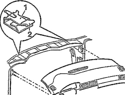
16.47. Before installing the panel, make sure that there are holders 1 on the instrument panel support bracket
The original text is available on the website: AudiManual.ru