
Repair Chevrolet Repair Toyota Repair Honda Repair AvtoVAZ Repair Mercedes-Benz Repair BMW Repair Opel
Home  |  Contacts  |  Sitemap  |    
English Русский
Български
Беларускі
Український
Српски
Hrvatski
Română
Polski
Slovenský
Magyar
AudiManual.ru


  • AUDI 80
  • AUDI 100
  • AUDI A3
  • AUDI A4
  • AUDI A6
  • AUDI A8
  • AUDI Q
  • OTHER
  • ARTICLES
B8 (2007-2015) B7 (2004-2008) B6 (2000-2006) B6 (2000-2006, petrol) B5 (1994-2001) B5 (1994-2001, petrol)

Removal and installation of automatic transmission components (Audi A4 B8)

  • Home
  • Audi A4
  • B8 (2007-2015)
  • Transmission
  • Automatic transmission 0AW
  • Removal and installation of automatic transmission components
            0
Table of contents: Removal and installation of the… ↓ Removal and installation of the… ↓ Removal and installation the gear… ↓

Removal and installation of the selector lock solenoid "N110"


Move the selector lever to position "P". Remove the E380 multimedia control panel. Remove the front ashtray.
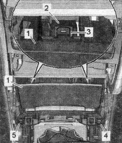
Move the selector lever to position «P». Remove the E380 multimedia control panel. Remove the front…


Unscrew the nuts "1, 3, 5, 6" a few turns, do not unscrew completely. This will lower the gearshift mechanism's functional block slightly, making it easier to remove later.
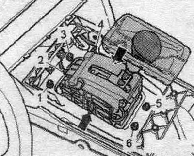
Unscrew the nuts «1, 3, 5, 6» a few turns, do not unscrew completely. This will lower the gearshift…


Risk of damage to the gearshift mechanism due to broken mounting brackets, protrusions or other parts. Pay attention to that. to ensure that no parts or objects end up inside the gear shift mechanism. If this happens, replace the gear shift mechanism. Unlock both protrusions "2" and "3" in the direction of the arrow, slightly lift cap "A" from the front and hold it in this position. This will prevent the protrusions from being fixed back into place.
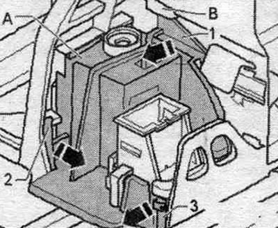


Risk of damage to the gearshift mechanism due to broken mounting brackets, protrusions or other…


Using a screwdriver, unlock the upper support bar "1" of the cap "in the direction of the arrow" through the holder "B" and remove the cap "A" upward. Disconnect the plug from the automatic transmission selector lock magnet "N110". Press the locking tabs "A" in the "arrow" switch and hold them in this position. If the "A" latch is broken, the gearshift mechanism functional unit must be replaced.
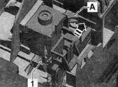
Using a screwdriver, unlock the upper support bar «1» of the cap «in the direction of the arrow»…


Tilt the automatic transmission selector lock magnet "N110" "in the direction of the arrow" so that the ball head "1" comes out of the gearshift mechanism control lever. Remove the selector lock magnet for the automatic transmission "N110".
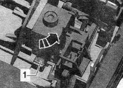
Tilt the automatic transmission selector lock magnet «N110» «in the direction of the arrow» so that…


Installation


Installation in reverse order. Turn the ball head "1" to the correct mounting position. position. Insert the selector lock solenoid "N110" from above at an angle into the gearshift mechanism and push it from below in the opposite direction of the arrow. Ball head "1" must be fully engaged in the gearshift control lever; if necessary, press it down with a small screwdriver. Secure the "N110" automatic transmission selector lock magnet to the "A" retainer. Place cover "A" on the "N110" automatic transmission selector lock magnet and carefully secure "1...3." Connect the plug connectors. Before the remaining assembly, check the operation of the gear shift mechanism. Install the front ashtray. Install the multimedia system control panel. "E380".


Removal and installation of the automatic gearbox selector sensor control unit "J587" with Tiptronic switch "F189"


Remove the automatic transmission shift knob. Remove the E380 multimedia control panel. Remove the front ashtray. Disconnect plug connector "1". Unlock the 4 "arrow" tabs and remove the automatic transmission selector sensor control unit "J587" with the Tiptronic switch "F189" in an upward direction. Ignore the "A arrows".
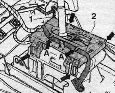
Remove the automatic transmission shift knob. Remove the E380 multimedia control panel. Remove the…


Installation


Installation in reverse order. Secure the J587 automatic transmission selector sensor control unit with the F189 Tiptronic switch to the four arrow-shaped tabs. Secure the Y26 automatic transmission selector position indicator panel wiring harness to the arrow-shaped tabs. Install the front ashtray. Install the multimedia system control panel. "E380". Install the automatic transmission lever handle.

Removal and installation the gear shift module functional unit


Remove the additional muffler or exhaust pipe. Using a 80-200mm release lever, detach the ball joint "1" of the selector cable from the gearbox lever. Remove the bolts "2" of the traction cable support. Release the gear selector cable. "Arrow" should not be taken into account. Remove the multimedia control panel "E380".
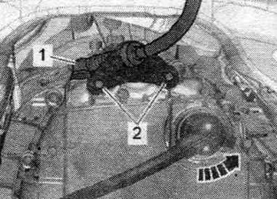


Remove the additional muffler or exhaust pipe. Using a 80-200mm release lever, detach the ball…


Remove the front ashtray. Disconnect plug connectors "2" and "4". Remove the damping mat above the gear shift mechanism. The damping mat is not shown in the figure. When removing the gear shift mechanism from underneath the vehicle, the assistance of a second mechanic is required.
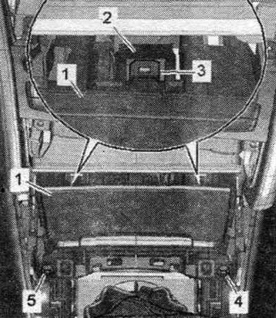
Remove the front ashtray. Disconnect plug connectors «2» and «4». Remove the damping mat above the…


Unscrew the bolts "1, 3, 5, 6". The "arrow" retainers are no longer installed, so after removing the bolts the shift mechanism may fall out. Remove the shift mechanism in a downward direction.
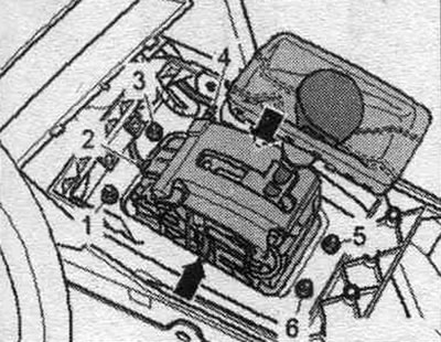
Unscrew the bolts «1, 3, 5, 6». The «arrow» retainers are no longer installed, so after removing…


Installation


Installation in reverse order. Before installation, lightly lubricate the ball joint of the selector cable with polyurea grease -G 052 142 A2-. The selector cable must not be bent or broken. When pressing, do not deform the gear shift lever, since this will make precise adjustment of the switch impossible. Install the selector cable support. Adjust the gear selector cable. Check the gear shift mechanism drive. Install add. muffler or exhaust pipe. Install the front ashtray. Install the multimedia system control panel. "E380".
The article was checked by auto expert Timur Bazhenov
This article is available at russian, bulgarian, belarusian, ukrainian, serbian, croatian, romanian, polish, slovak, hungarian

Share information:
Previous articles
Audi A4 B8: Automatic transmission 0AW
Next articles

Electrical, electronic components and their location
Dual mass flywheel
Filling volumes and checking oil levels
Location of markings on the checkpoint and decoding
Selector lever cable — removal, installation and adjustment
ATF drain for flushing
Cover, automatic transmission control unit «J217», hydraulic…
Threaded plugs for drain and inspection holes of the gearbox


Similar articles on other Audi car models:
Vacuum Pump (with Automatic Transmission) — Removal and… Audi 80 B3 (1986-1991, petrol)
Automatic transmission Audi 100 C3 (1982-1990, diesel)
Automatic transmission Audi A3 Type 8L (1996-2003)
Automatic transmission Audi A6 C5 (1997-2004)
Automatic transmission Audi A8 D2 (1994-2002)
Removal and installation of the automatic transmission and… Audi Q7 Typ 4L (2005-2015, diesel)
Removal and installation the automatic transmission selector… Audi A2 (1999-2005)
Link to this page in different formats


Visitor comments

No comments yet


How much will 20 + 42 =


A4(B8, 2007-2015) 
  • General information
  • Operating instructions
  • Power unit
  • Petrol engines 1.8 l
  • Petrol engines 1.8/2.0 l
  • Petrol engines 3.0 l
  • Petrol engines 3.2 l
  • Fuel system (petrol)
  • Diesel engines 2.0 l (CA*)
  • Diesel engines 2.0 l (CJCB)
  • Diesel engines 2.7/3.0 l
  • Diesel engines 3.0 l
  • Fuel system (diesel)
  • Transmission
  • Manual gearbox 0B1
  • Manual gearbox 0B2
  • Manual gearbox 0B3
  • Manual gearbox 0B4
  • Automatic transmission 0B5
  • Automatic transmission 0B6
  • Automatic transmission 0AW
  • All-wheel drive system
  • Chassis
  • Front suspension
  • Rear suspension
  • Brake system
  • Steering system
  • Body
  • Exterior
  • Interior
  • Seats
  • Doors, locks and windows
  • Security system
  • Heating and air conditioning
  • Electrical equipment
  • Audio system
  • Power devices
  • Equipment and devices
  • Lighting and lamps
  • Electrical circuits
 
A4(B7, 2004-2008) 
  • General information
  • Introduction to manual
  • Troubleshooting
  • Operating instructions
  • Maintenance
  • Power unit
  • Petrol engines 2.0 (ALT)
  • Petrol engines 2.0 (TFSI)
  • Petrol engines 1.8 (MPI)
  • Diesel engines
  • Cooling system
  • Air conditioner
  • Fuel and exhaust system
  • Ignition system
  • Starting and charging
  • Transmission
  • Clutch
  • Manual gearbox
  • Automatic gearbox
  • Drive shafts
  • Chassis
  • Brake system
  • Front suspension
  • Rear suspension
  • Steering
  • Body
  • Exterior
  • Interior
  • Electrical equipment
  • Equipment and devices
  • Lighting and signaling
  • Windscreen wipers and washers
  • Electrical diagrams
  • Electrical diagrams (since 2007)
 
A4(B6, 2000-2006) 
  • General information
  • Vehicle Description
  • User manual
  • Maintenance
  • Power unit
  • Gasoline engine
  • Diesel engine
  • Lubrication system
  • Cooling system
  • Supply system
  • Injection system
  • Exhaust system
  • Ignition and control
  • Transmission
  • Gear box
  • Clutch and drive shafts
  • Chassis
  • Brake system
  • Car suspension
  • Steering
  • Body
  • Heating and ventilation
  • Exterior (external elements)
  • Interior (internal elements)
  • Electrical equipment
  • Power devices
  • Lighting and appliances
  • Electrical circuits
 
A4(B6, 2000-2006, petrol) 
  • General information
  • Introduction to the guide
  • Car care
  • Power unit
  • Engine repair
  • Lubrication system
  • Cooling system
  • Injection and control system
  • Ignition system
  • Power and exhaust system
  • Transmission
  • Clutch and drive shafts
  • Car gearbox
  • Chassis
  • Suspension and wheels
  • Steering
  • Brake system
  • Body
  • Interior
  • Exterior
  • Electrical equipment
  • Equipment and devices
  • Lighting and signaling
  • Power devices
  • Electrical circuits
 
A4(B5, 1994-2001) 
  • General information
  • Introduction to the guide
  • Car care
  • Maintenance (gasoline)
  • Maintenance (diesel)
  • Power unit
  • Gasoline engines
  • Diesel engines
  • Engine overhaul
  • Cooling system
  • Fuel injection (gasoline)
  • Fuel system (diesel)
  • Exhaust system
  • Ignition system
  • Transmission
  • Clutch
  • Mechanical gearbox
  • Automatic gearbox
  • Drive shafts
  • Chassis
  • Brake system
  • Car suspension
  • Steering
  • Body
  • Exterior
  • Interior
  • Doors, locks and windows
  • Heating and ventilation
  • Electrical equipment
  • Power devices
  • Equipment and devices
  • Electrical circuits
 
A4(B5, 1994-2001, petrol) 
  • General information
  • Vehicle description
  • Maintenance
  • Power unit
  • Engine repair
  • Turbocharging
  • Exhaust system
  • Cooling system
  • Ignition system
  • Fuel system
  • Motronic injection system
  • MPI and MPFI injection system
  • Transmission
  • Clutch
  • Gearbox and shafts
  • Chassis
  • Steering
  • Car suspension
  • Brake system
  • Wheels and tires
  • Body
  • Heating and ventilation
  • Body parts
  • Electrical equipment
  • Fuses and relays
  • Power devices
  • Lighting and lamps
  • Tools and devices
  • Electrical circuits
 
AudiManual.ru © 2017-2026 · Mobile version · Feedback · Sitemap: EN BG BY UA RS HR RO PL SK HU · Site search · News and articles
80 B2 · 80 B3 petrol · 80 B3 · 80 B4 · 100 C3 diesel · 100 C3 petrol · 100 C3 · 100 C4 petrol · 100 C4 · A3 Type 8L · A4 B5 petrol · A4 B5 · A4 B6 petrol · A4 B6 · A4 B7 · A4 B8 · A6 C4 · A6 C5 · A6 C5 Allroad · A8 D2 · Q5 Type 8R · Q7 Typ 4L · Audi A2 ·
This site uses cookies 🍪. Click the button to accept this fact.