
Table of contents: Removal and installation the outer… ↓ Removal and installation the stone… ↓ Allroad trims and overlays ↓ Replacing the fender lining ↓ Removal and installation the… ↓ Replacing the mounting plate ↓ Removal the front sill trim ↓ Replacing the sidewall trim ↓
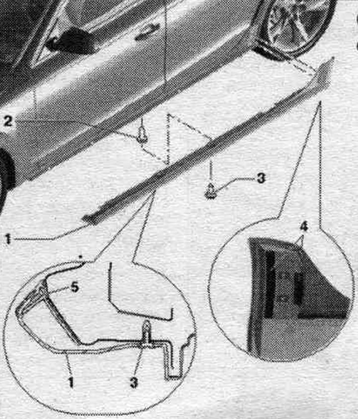
Removal and installation the outer threshold trim
The threshold trim is secured to the threshold with adhesive tape. Dismantling without damage is not provided.
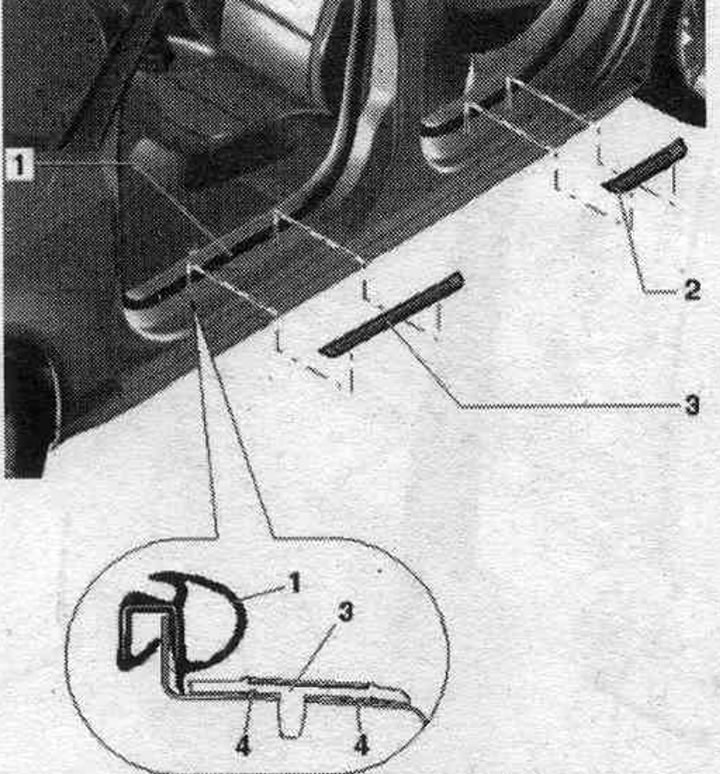
1. Internal door seal.
2. Rear door sill trim: removal: heat the door sill trim with a hair dryer and remove it upwards; installation: The lower beam in the gluing area must be cleaned of dust and grease, heat the gluing surface with a hair dryer to approximately 40°C, remove the protective film from the adhesive tape, insert the threshold trim with centering pins into the threshold and press firmly, starting from the front towards the back.
3. Front threshold trim: the removal and installation procedure is similar to the work with the rear. threshold overlay.
4. Adhesive tape: Please remove the protective film before installation.
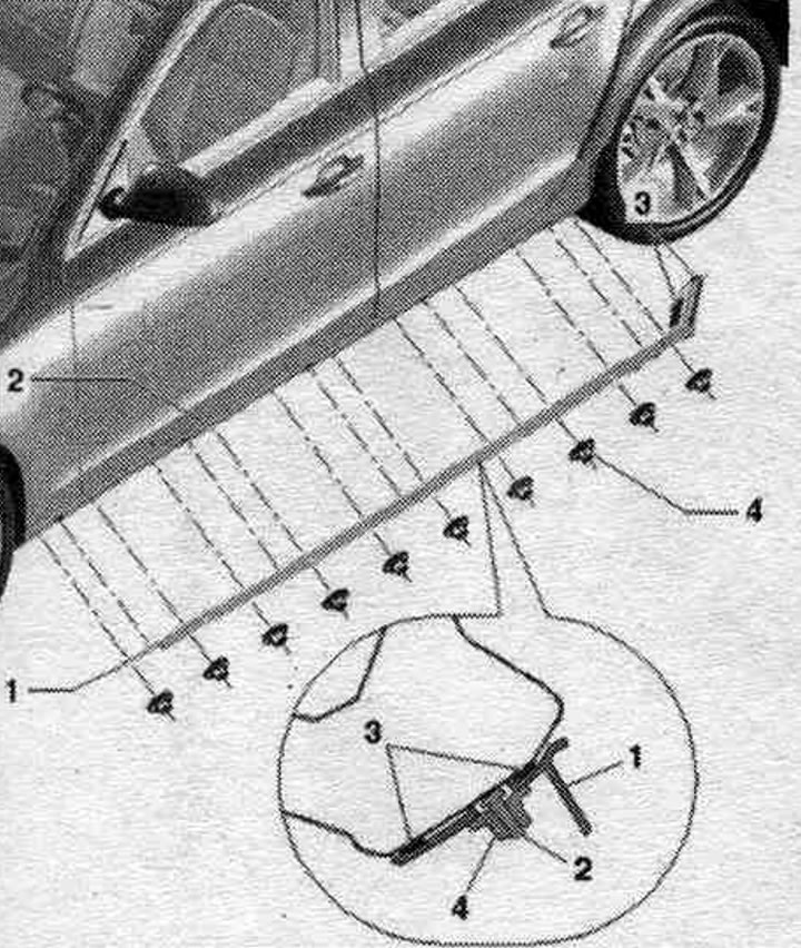
Removal and installation the stone chip protection strip
The bar for protection against stone impacts is additionally secured. strips of adhesive tape on the threshold. Dismantling without damage is not provided. When removing the protective strip, the clamps also break and must be replaced.
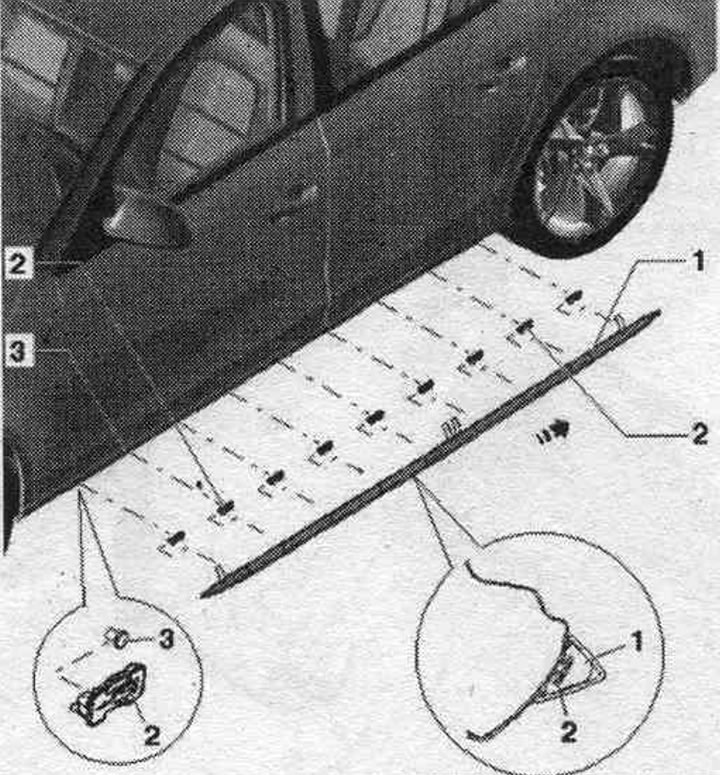
1. Protective strip against stone impacts: removal: heat the glued areas with a hair dryer and gradually remove the protective strip from the side of the threshold; installation: Turn the tabs on the protective film upwards so that they are accessible when the protective strip is installed on the lower beam, place the protective strip against stone impacts on the clamps, starting from the back and moving forward until it stops; observe the sequence of removing the tongues and press the protective strip firmly and evenly against the threshold. When removing the protective strip, the clamps are removed from the mounting bolt and must be replaced. The lower beam in the area where the adhesive tape is applied must be cleaned of dust and grease.
2. Clamp: 9 pcs.; the direction for installing the clamp is set; install and snap the clamps onto the bolt, taking into account the installation direction; align the clamps along the threshold.
3. Fingers.
Sequence of tongue removal
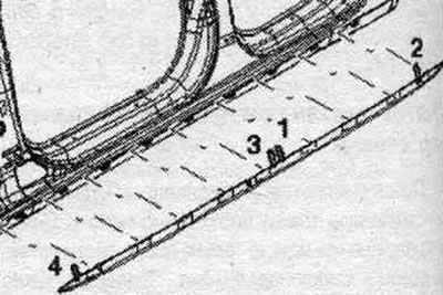
Remove the tongues in sequence. "1"; "2";"3" and "4". Press the protective strip firmly and evenly against the side member.
Allroad trims and overlays
Note: The glued-on pads can only be replaced; their removal without damage is not possible. If necessary, remove any remaining adhesive from the body. Clean the adhesive surfaces of the body with a cleaner "0 009 40104". There should be no dust or oil on the bonding surface. Before gluing, heat the bonding surfaces and overlays to approximately 40°C. When installing, the overlays must be installed strictly in place; subsequent adjustment of the position is not possible. After successful installation, press the linings with the pressure roller "3356".
Replacing the fender lining
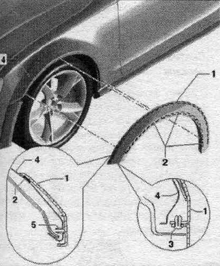
1. Trim: Removal: Remove the clip under the fender liner, heat the adhesive surface with a hair dryer and gradually remove the trim; installation: Unscrew the protective films on the sides so that they are accessible when the wing trim is installed, to act as tabs for removal; when installing, place it strictly along the contour through the centering pins, starting from the front and back, remove the protective film by the tabs between the wing and the trim and gradually press it with your hand, press the clamp into the trim.
2. Adhesive tape: Before installing the overlay, slightly pull the protective film and bend it at the sides to act as tabs for removal.
3. Expansion piston.
4. Wing.
5. Centering pin.
Removal and installation the threshold trim
1. Threshold trim: to remove, unscrew the bolts from below; starting from the front, remove the threshold trim from the bottom up from the fastening strip; when installing, install the cladding into the fastening strip only from above, press the cladding from above into the fastener and secure it from below with bolts. If the old cladding is being reinstalled, replace the adhesive tapes.
2. Clamp.
3. Bolt: 1.5 Nm.
4. Adhesive tape: included in the scope of delivery of new parts; replace when reinstalling the threshold trim.
5. Velcro closure.
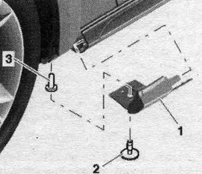
Replacing the mounting plate
1. Mounting plate: unscrew the nuts and remove the mounting plate; before installation, remove the protective film from the adhesive strips, place the strip along the contour and press firmly.
2. Fingers.
3. Adhesive tape.
4. Nut: 2 Nm.
Removal the front sill trim
To remove, unscrew screw "2" and remove the front sill trim "1". When installing, tighten the bolt to a torque of 2.5 Nm.
1. Front threshold trim.
2. Screw.
3. Clamp.
Replacing the sidewall trim
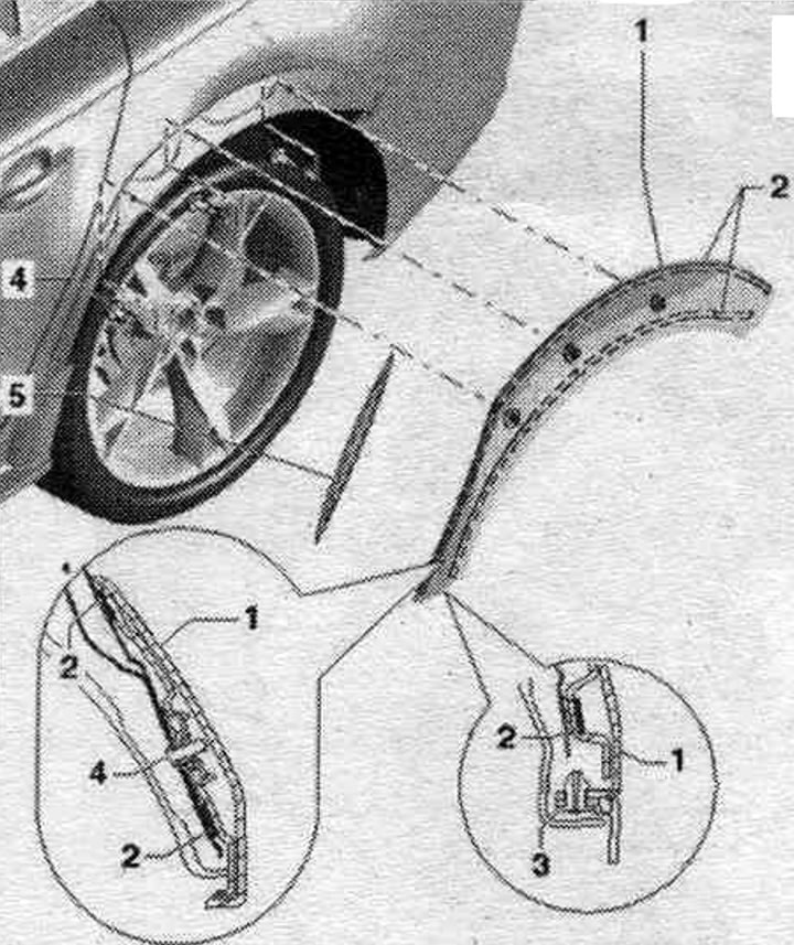
1. Side panel trim: removal: unscrew the bolts from the bottom of the fender liner, remove the clamp under the fender liner, heat the adhesive surface with a hair dryer and gradually remove the trim; installation: Unscrew the protective films on the sides so that they are accessible when the trim is installed on the side panel, as tabs for removal, during installation, install strictly along the contour, maintaining a gap to the threshold trim and door trim, remove the protective film by the tabs between the side panel and the trim and gradually press it with your hand, tighten the screws in the following order: in the middle, at the back and in the front, press the clip into the trim.
2. Adhesive tape: Please remove the protective film before installation.
3. Fender liner.
4. Bolt: 2.5 Nm.
5. Rear overlay. doors: to remove, heat the adhesive surface with a hair dryer and gradually remove the cover; when installing, apply the overlay strictly along the contour and gradually press it with your hand.
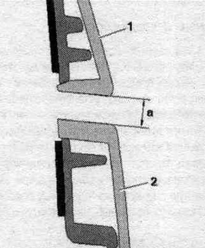
Sidewall/sill panel gap
Check the gaps using the "T40038/8" template and adjust if necessary. Press the side panel trim "1" with an indent "a" from the threshold trim "2".
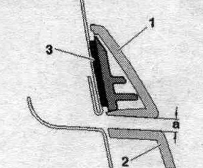
Door/side panel gap
Press door trim "1" with an indent "a" = 2.5 mm from the side panel trim "2". Pay attention to the parallelism of the gaps.
(The original article is available on the online resource: audimanual)