
Caution: Depending on the engine/gearbox combination, the inner joint is designed as a constant velocity joint or a tripode joint. The tripode joint has 3 rollers instead of 6 balls, which are offset by 120° from each other and are located on the tripode star.
Outer hinge
Removal
1. Remove the shaft, refer to Section Removal and installation the drive shaft.
2. Clamp the shaft through protective pads in a vice.
3. Remove the clamps and slide the protective cover back.
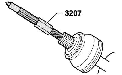
4. Screw the pressure screw (3207) with a guide for the M14/M16 thread into the joint journal so as to remove the joint from the shaft.
5. Remove the retaining ring.
Installation
1. Place the cover on the shaft.
Warning: The boot and the place where it fits on the shaft must not be lubricated.
2. Install a new retaining ring.
3. Inject 50g of grease into the inside of the joint.
4. Screw the previously used screw into the hinge as shown in the accompanying illustration.
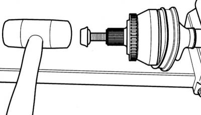
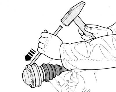
5. Press the joint onto the shaft using a plastic hammer until the retaining ring is secured.
6. Remove the old screw.
7. Inject 40 g of grease into the joint from the boot side.
8. Lubricate the outer hinge.
Warning: Observe the specified amount of lubrication, refer to Specifications.
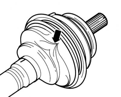
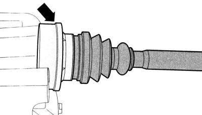
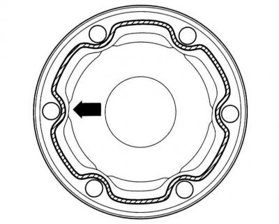
Warning: The cover is often compressed when placed on the hinge body. This creates a vacuum in the hinge, which causes the cover to be pressed in (arrow on the accompanying illustration). Therefore, when installing the cover, use a screwdriver on a small diameter to fill the hinge with air so as to ensure pressure equalization.
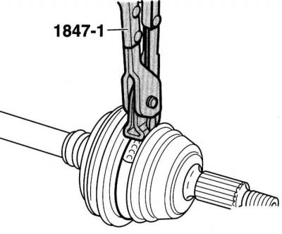
9. Using special pliers, such as HAZET 1847-1, squeeze the clamps on the large and small diameters of the hinge.
Plastic case
1. Tighten the clamps on the large and small diameters.
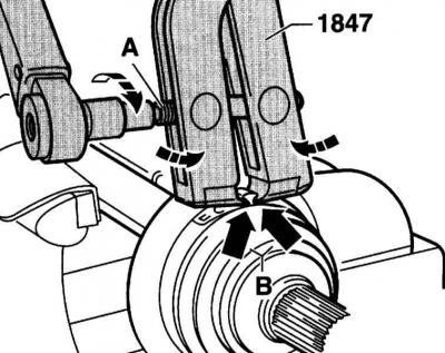
2. Outer hinge: For clamping the clamps (alloy steel) the special HAZET 1847 pliers shown in the illustration must be used, otherwise the required compression force will not be achieved. The pliers must be installed as shown in the illustration. The working edges of the pliers must be in the corners (B). In this position, the screw (A) is tightened with a torque of 20 Nm. The clamp on the small diameter is clamped in a similar manner.
Warning: The thread of the clamping screw of the pliers must have a light movement, otherwise it must be pre-lubricated with MoS2 grease. If the thread has a heavy movement, for example due to contamination, the required tightening torque of the screw is not achieved.
Internal constant velocity joint
Removal
1. Remove the cover using a suitable punch.
2. Remove the retaining ring.
3. Remove grease from the joint and mark the position of the joint relative to the shaft.
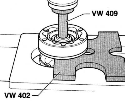
4. Clamp the shaft by the joint in a vice as shown in the accompanying illustration.
5. The assistant must hold the shaft horizontally to avoid damaging it.
6. Using a small flat chisel, slightly bend the edge of the lid (arrow).
7. Install the cover in place using the appropriate mandrel.
8. Press the joint off the shaft.
9. Remove the cover with the lid.
Installation
1. Apply grease to the clean surface of the inside of the lid (shaded area in the accompanying illustration). Apply a 2-3 mm wide bead of sealant around the holes on the inside. AUDI service stations use sealant D 454 300 A2 for this.
Warning: The shaft, boot and mating surface must be free of grease.
2. Place the new cover and cap on the shaft.
3. Add 85g of lubricant into the case.
4. Secure the hinge with tape (arrow on the accompanying illustration), so that it doesn't fall apart.
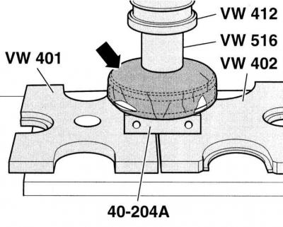
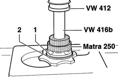
5. Press the joint until it stops on the appropriate press. AUDI service stations use a special tool for this, shown in the illustration.
Caution: Install the joint hub with the chamfer on the inside diameter (splines) on the joint. The 40-204A tool and the mating surface on the shaft must be free of grease.
6. Install a new retaining ring.
7. Inject 35g of grease through the ball races into the joint.
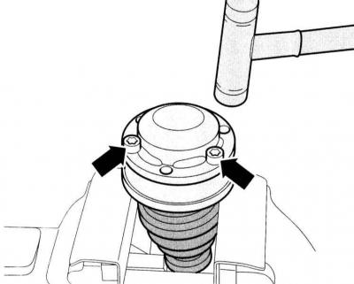
8. Using the screws (arrows), align the cover with the lid in relation to the holes.
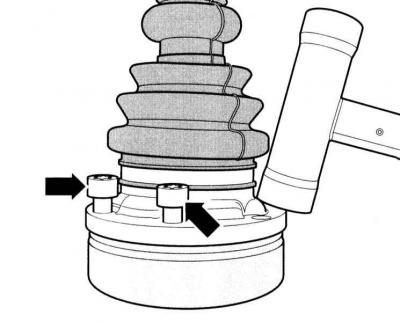
Warning: It is necessary to set it very precisely, because after assembly it will be impossible to do it.
9. Install the cover and lid back into place using a plastic hammer.
10. Remove any spilled grease immediately.
11. Align the new cover with screws (arrows) with the bolt holes.
Warning: It is necessary to set it very precisely, because after assembly it will be impossible to do it.
12. Install the cover and lid back into place using a plastic hammer.
13. Remove any spilled grease immediately.
14. Reinstall the drive shaft, refer to the appropriate Section.
The original article is posted on the resource: AudiManual.ru