
Repair Chevrolet Repair Toyota Repair Honda Repair AvtoVAZ Repair Mercedes-Benz Repair BMW Repair Opel
Home  |  Contacts  |  Sitemap  |    
English Русский
Български
Беларускі
Український
Српски
Hrvatski
Română
Polski
Slovenský
Magyar
AudiManual.ru


  • AUDI 80
  • AUDI 100
  • AUDI A3
  • AUDI A4
  • AUDI A6
  • AUDI A8
  • AUDI Q
  • OTHER
  • ARTICLES
B4 (1991-1996) B3 (1986-1991) B3 (1986-1991, petrol) B2 (1979-1986)

Checking, removing and installing the thermal time switch (K-, KE-Jetronic not suitable for NG, 6A) (Audi 80 B3)

  • Home
  • Audi 80
  • B3 (1986-1991)
  • Power unit
  • Injection system (gasoline)
  • Checking, removing and installing the thermal time switch (K-, KE-Jetronic not suitable for NG, 6A)
            0
Table of contents: Examination ↓ Removal ↓ Installation ↓
The thermal time switch limits the injection time of the cold start valve depending on the coolant temperature.

A faulty thermal time switch will cause difficulties with cold starting.

Examination


When checking, the engine must be cold, the coolant temperature below 30°C. If necessary, remove the thermal time switch and cool it in a water bath.

Disconnect the high voltage wire - terminal 4 - on the ignition distributor (central cable) and short it to ground. If necessary, use an auxiliary cable of the same cross-section.

Disconnect the cold start valve plug and connect a voltage tester or test lamp to the plug contacts. The thermal time switch is tested through the cold start valve connector.

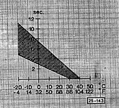
Turn on the starter for 10 sec. The LED of the test device should light up for 1-8 sec. depending on the temperature of the thermal time switch. The time of the first switch-on depends on the air temperature and should be within the permissible limits, see the diagram. For example, the coolant temperature is +10°C, the switch-on time is 2-2.5 sec.

If the tolerance is not met, replace the thermal time switch.

Connect the high voltage wire with the ignition distributor plug to the cold start valve.
Connect the high voltage wire with the ignition distributor plug to the cold start valve.


Removal


Disconnect the plug on the thermal time switch.

Unscrew the switch.

Installation


Screw on the thermal time switch and connect the plug.

Check the coolant level and top up if necessary.
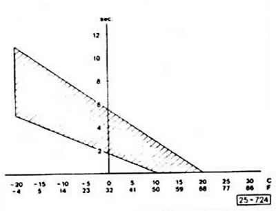
Diagram for the temperature and time sensor for a 5-cylinder engine

Diagram for the temperature and time sensor for a 5-cylinder engine
The article was checked by auto expert Elisey Ermolaev
This article is available at russian, bulgarian, belarusian, ukrainian, serbian, croatian, romanian, polish, slovak, hungarian

Share information:
Previous articles
Audi 80 B3: Injection system (gasoline)
Next articles

Removal, installation, testing of cold start valve (K-,…
Removal and installation the lambda probe
Checking the adjusting lever and control piston (K-, K-Jetronic,…
Checking and setting the free travel of the back-up valve (K-,…
Checking the additional air valve (engines 90, 102, 112 hp;…
Fuel pump
Checking the fuel pump


Similar articles on other Audi car models:
Cooling Fan Thermal Switch — Checking, Removing and Installing Audi 100 C3 (1982-1990, diesel)
Checking the cooling fan thermal switch Audi A3 Type 8L (1996-2003)
Checking, removing and installing the thermostat Audi A4 B7 (2004-2008)
Installing and checking the crankshaft Audi A6 C4 (1994-1997)
Ignition switch Audi A8 D2 (1994-2002)
Checking, cleaning, removing the water drainage box and… Audi Q5 Type 8R (2008-2017)
Engine — Checking Oil Level Audi A2 (1999-2005)
Link to this page in different formats


Visitor comments

No comments yet


How much will 13 + 30 =


80(B4, 1991-1996) 
  • General information
  • User manual
  • Maintenance
  • Troubleshooting
  • Power unit
  • Engine
  • Cooling system
  • Heating and ventilation
  • Petrol injection
  • Diesel fuel system
  • Fuel system
  • Exhaust systems
  • Ignition system
  • Transmission
  • Clutch
  • Car gearbox
  • Chassis
  • Brake system
  • Suspension and steering wheel
  • Body
  • Body and trim
  • Electrical equipment
  • Electrical system
  • Electrical circuits
 
80(B3, 1986-1991) 
  • General information
  • Repair characteristics
  • Maintenance
  • Power unit
  • Gasoline engine
  • Diesel engine
  • Engine lubrication system
  • Fuel system (gasoline)
  • Injection system (gasoline)
  • Fuel system (diesel)
  • Ignition system
  • Cooling system
  • Heater
  • Exhaust system
  • Transmission
  • Clutch and gearbox
  • Chassis
  • Steering
  • Brake system
  • Car suspension
  • Body
  • Body elements
  • Electrical equipment
  • Power devices
  • Lighting and appliances
  • Electrical circuits
 
80(B3, 1986-1991, petrol) 
  • General information
  • User manual
  • Maintenance
  • Power unit
  • Engine 4-cylinder
  • Engine 5-cylinder
  • Cooling system
  • Fuel and exhaust systems
  • Ignition system
  • Transmission
  • Clutch
  • Mechanical transmission
  • Automatic transmission
  • Drive shafts
  • Chassis
  • Brake system
  • Suspension
  • Steering
  • Body
  • Exterior
  • Interior
  • Electrical equipment
  • Equipment and devices
  • Electrical circuits
 
80(B2, 1979-1986) 
  • General information
  • User manual
  • Power unit
  • Engine FZ
  • Engine EP, YP, YZ, DT, DS, DZ
  • Transmission
  • Clutch
  • 4 speed gearbox
  • 5 speed gearbox
  • Front wheel drive
  • Chassis
  • Front suspension
  • Rear suspension
  • Steering
  • Brake system
  • Electrical equipment
  • Equipment and devices
  • Electrical circuits
 
AudiManual.ru © 2017-2026 · Mobile version · Feedback · Sitemap: EN BG BY UA RS HR RO PL SK HU · Site search · News and articles
80 B2 · 80 B3 petrol · 80 B3 · 80 B4 · 100 C3 diesel · 100 C3 petrol · 100 C3 · 100 C4 petrol · 100 C4 · A3 Type 8L · A4 B5 petrol · A4 B5 · A4 B6 petrol · A4 B6 · A4 B7 · A4 B8 · A6 C4 · A6 C5 · A6 C5 Allroad · A8 D2 · Q5 Type 8R · Q7 Typ 4L · Audi A2 ·
This site uses cookies 🍪. Click the button to accept this fact.