
Check the timing belt tension.
Rotate the crankshaft until the TDC mark on the flywheel matches the pointer in the gearbox housing. At the same time, the camshaft cams of the 1st cylinder should be facing up to the left and up to the right. In this position, you can insert the locking ruler 20665A into the camshaft spline.
Lock the camshaft with a ruler. The ruler (VW2065A) has a curve to prevent the camshaft from turning. It needs to fit into the camshaft spline.
If the ruler does not fit, turn the crankshaft so that the ruler can be inserted. Center the ruler as follows.
Turn the camshaft so that the end of the ruler rests against the cylinder head. Measure the gap at the other end of the ruler using a feeler gauge.
Insert a half-thickness feeler gauge between the ruler and the cylinder head. Turn the camshaft so that the ruler is pressed against the feeler gauge. Insert a second feeler gauge of the same size at the other end of the ruler.
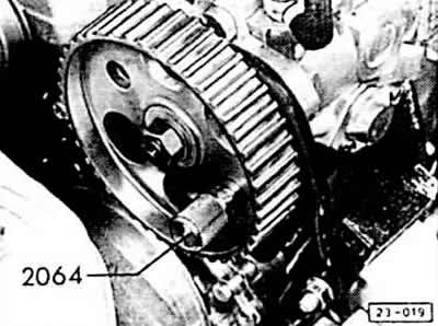
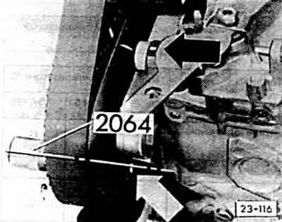
The 2064 mandrel should now fit into the hole in the fuel pump wheel and pump holder. If the mandrel cannot be inserted into the hole, the engine control must be readjusted.
To do this, turn the crankshaft so that the TDC marks of the piston of the 1st cylinder coincide with the indicator on the gearbox housing and at the same time the camshaft cams for the 1st cylinder are facing up to the left and up to the right.
Lock the camshaft with a ruler.
Loosen the camshaft wheel mounting bolt by ½ turn. Knock the camshaft wheel off the cone with one blow using a hammer and a ∅ 6 mm punch from behind through the hole in the toothed belt shield.
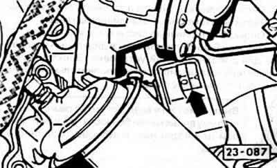
Turn the fuel pump wheel so that the marks on the fuel pump wheel and console coincide -black arrow-.
Lock the pump wheel with a suitable rod.
Note: If required for proper installation, remove timing belt and tighten after installation.
Tighten the camshaft wheel mounting bolt to 45 Nm. Remove the adjusting ruler and rod.
Check the moment the injection pump starts feeding.