
2. Mark the position of the clutch housing and flywheel relative to each other.
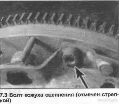
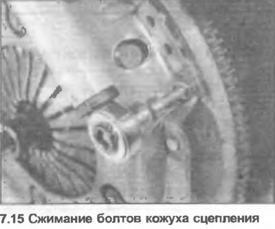
3. Lock the flywheel, then unscrew the clutch housing bolts in a diagonal sequence (photo). After unscrewing the bolts two or three turns, check that the coating is not stuck on the mounting pins. If necessary, use a screwdriver to release the coating.
4. Remove all bolts, then lift the clutch cover and friction disc off the flywheel.
5. Clean the cover, disc and flywheel. Do not inhale the dust, as it contains asbestos, which is harmful to health.
6. Check the condition of the diaphragm spring pins. If the wear depth exceeds 0.3 mm, the cover assembly must be replaced.
7. Check the condition of the pressure plate. Light wear is acceptable, but if it is excessive, the cover assembly must be replaced.
8. Check the condition of the friction disc linings for cracks and grease contamination. Linings are considered excessively worn if they are worn down to the rivets. Check the condition of the disc hub and grooves by temporarily installing it on the gearbox input shaft. Replace the friction disc as needed.
9. Check the condition of the flywheel friction surface. If there is excessive wear, the flywheel can be reground, otherwise - replace it.
10. Before assembly, check that all parts are clean. Apply high-temperature grease to the grooves of the friction disc hub. Note that the new pressure plate and clutch housing are coated with a protective lubricant. It is permissible to clean the lubricant only from the contact surface of the friction disc lining. Removing lubricant from other areas will reduce the service life of the clutch.
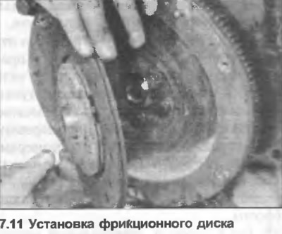
11. Begin assembly by placing the friction disc on the flywheel, with the hub side with the torsion springs facing outward (photo).
12. Position the clutch housing on the disc, install it on the pins. If the old coating is installed, align the previously made marks.
13. Insert and manually tighten the bolts to secure the cover in position.
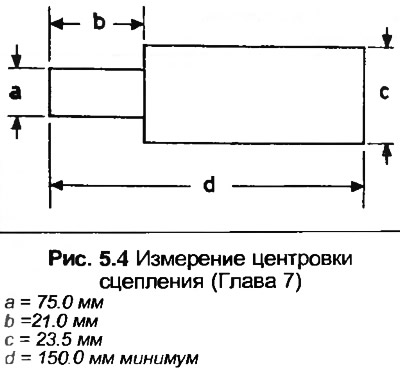
14. The friction disc must now be centred to ensure correct alignment of the gearbox input shaft with the hub bearing in the crankshaft. To do this, you can use a tool, or a wooden punch, made to the dimensions given in Fig. 5.4. Insert the tool through the friction disc into the hub bearing and make sure it is centred (photo).
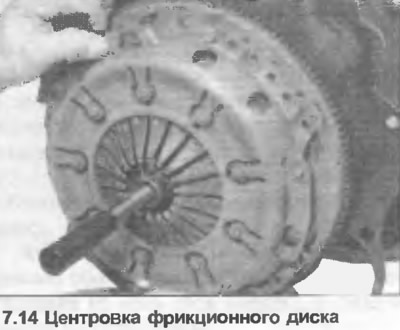
15. Tighten the clutch housing bolts evenly in a diagonal sequence until the specified tightening torque is reached Specification, then remove the alignment tool (photo).
16. Before installing the gearbox, check the smoothness and softness of the release bearing operation, if necessary, replace it as described in Chapter 8.
17. Install the engine or gearbox as described in Sections 1 or 6.