
Removal
Remove the right front wheel. Remove the noise insulation screen.
Instructions: Mark the direction of rotation of the poly V-belt with chalk or a felt-tip pen. Changing the direction of rotation of a previously used belt may damage it.
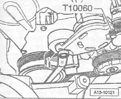
To loosen the tension of the poly V-belt, tilt the tensioner with a spanner in the direction of the "arrow". Fix the tensioner by installing the locking pin "T10060 A" or "T10060" in the locking holes. Remove the poly V-belt.
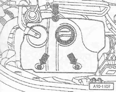
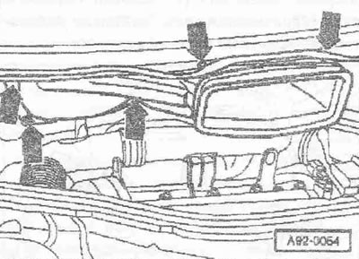
Remove the engine hood. Remove the engine cover "arrows". Remove the noise insulation screen located below, for which disconnect the crankcase ventilation hose.
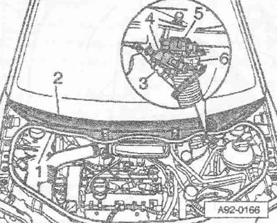
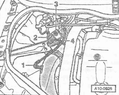
Using a screwdriver, remove caps 3 and "4" from the windshield wiper arms. Loosen the nuts on both arms a few turns. Release arms "1" and "2" by slightly tilting them on the windshield wiper axles. Loosen the nuts completely and remove the windshield wiper arms. Disconnect the windshield washer fluid pipe "3". Disconnect the plug connectors "4" and "5" of the heated washer nozzles. Release the hose clamp "6" and use the hose clamp pliers "VAG 1921" to remove the drain hose from the fairing grille. Shine the rubber seal "1" of the fairing grille. Remove the fairing grille "2". Release the windshield washer fluid pipe.
Unscrew the bolts and nuts of the "arrows". Remove the fresh air intake duct and hang it on the right side of the car.
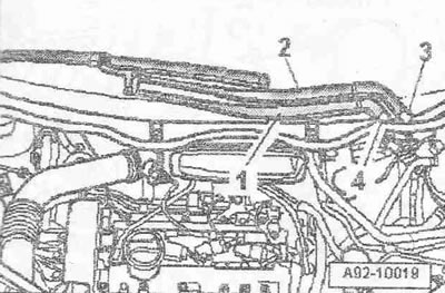
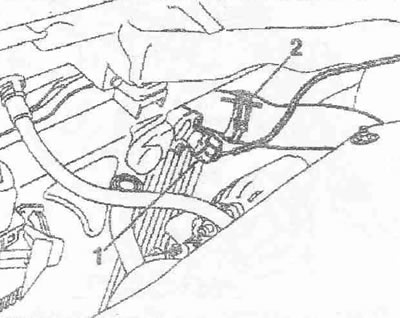
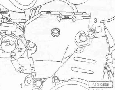
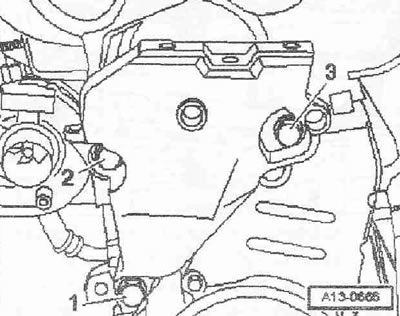
Disconnect plug connector "2" of air flow meter "g70". Disconnect vacuum hose "1". Release hose clamp "4" and remove air duct with air flow meter "G70". Disregard item "3".
Remove air hose "2" connecting the intercooler and intake manifold. Ignore item "1".
Unscrew the poly V-belt tensioner "arrow".
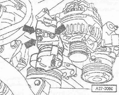
Remove the top cover of the gear belt by loosening the locking brackets "arrows".
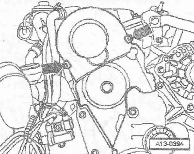
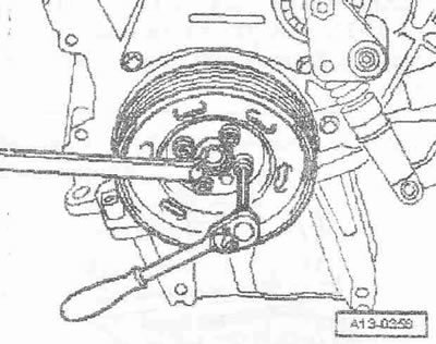
Loosen the damper while holding the central bolt with a spanner.
Unscrew the middle and lower covers of the toothed belt "arrows".
Remove the lower bolt "1" of the engine mount. Bolts "2" and "3" will be removed later.
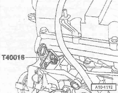
Screw the front right cargo eye "T40016" to the cylinder head.
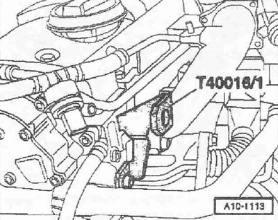
Screw the rear left cargo eye "t40016/1" to the cylinder head.
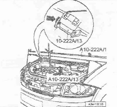
Install the "10-222 A" crossbar with the "10-222 A/13" adapters on the connecting edges of the wings. The lead screw of the crossbar faces forward.
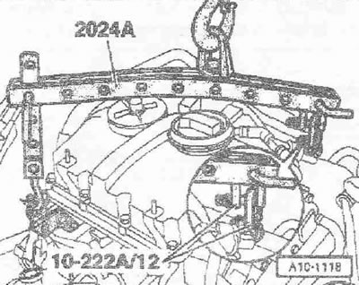
Install 2 "10-222 A/12" earrings on the rear left cargo eye "T4001b" on the cylinder head. Secure the "2024 A" hanging device to the engine and to the "10-222 A" crossmember, as shown in the figure.
Instructions. To align the center of gravity of the power unit, the hook bars must be inserted as shown in the figure. The hooks and locking pins of the hanging device must be secured with cotter pins.
Tighten the engine on the lead screw. Do not lift the engine. Unscrew nut "3" only when replacing the engine mount.
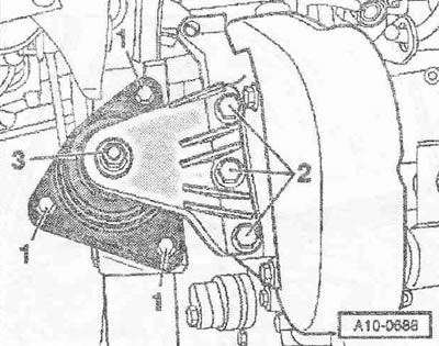
Unscrew bolts "1" and "2" and remove the bracket with the engine mount. Unscrew bolts "2" and "3" and remove the engine support.
Caution! The engine may only be turned by the crankshaft in the direction of engine rotation (clockwise). To turn the engine shaft, install the central bolt on the crankshaft.
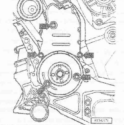
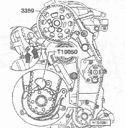
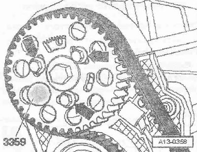
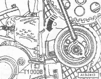
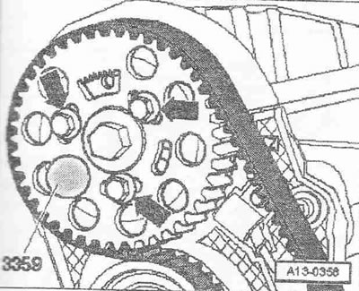
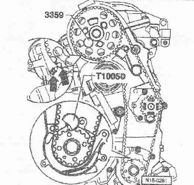
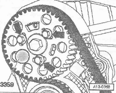
Bring the crankshaft to the TDC position of the first cylinder. The arrow with the inscription "3Z" on the rear cover of the toothed belt should point to the toothed ring of the hub "arrows". Fix the camshaft hub using the locking pin "3359". Fix the crankshaft gear using the crankshaft stopper "T10050".
Instructions: The stopper should be installed on the toothed belt pinion only from the end face of the toothed rim.
The marks on the toothed belt gear and the crankshaft stopper "T10050" must be opposite each other. The journal of the crankshaft stopper "T10050" must enter the hole of the sealing flange.
Mark the direction of rotation of the toothed belt with chalk or a felt-tip pen. Unscrew the bolts "arrows" of the camshaft gear.
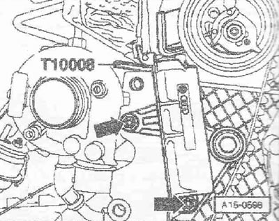
Insert the Allen key into the Allen hole until it stops and turn the tension roller counterclockwise "arrow" until the tensioner is locked with the locking plate "T10008".
Instructions: To avoid damage, insert the Allen key until it stops. The timing belt tensioner is equipped with an oil stop, so it can only be compressed gradually and with uniform force.
Loosen the tension roller fastening nut.
Unscrew the "arrow" bolts and remove the toothed belt tensioner. Remove the toothed belt.
Installation (valve timing adjustment)
The camshaft is fixed with pins "3359". The crankshaft is fixed with crankshaft stopper "T10050". The tension roller is locked with the help of locking plate "T10008".
Instructions. Adjust the timing belt only when the engine is cold. When turning the camshaft, one of the crankshaft pistons must not be at TDC. Risk of damage to valves/piston crown.
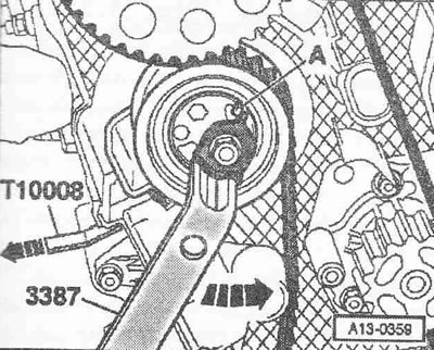
Do not screw in the bolts "arrow" completely. The camshaft gear must rotate and must not wobble. Turn the camshaft gear in the grooves clockwise until it stops. Install the toothed belt on the camshaft gear, tension roller, crankshaft gear and, last of all, on the coolant pump gear. Install the toothed belt tensioner. Adjust the tension of the toothed belt as follows: turn the eccentric with a 2-hole wrench "3387" counterclockwise "arrow" until it stops "A". Remove the locking plate "T10008".
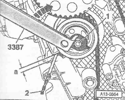
To protect against cuts, wrap the tip and cutting edges of the 7 mm drill with insulating tape. Slowly turn the key clockwise "arrow" until the 7.0 mm drill "pos. 2" passes freely between the lever and the tensioner body. Distance "a" = 7.0±1.0 mm.
Instructions. Distance "a" decreases when tightening the tension roller nut, set it initially large. When the engine warms up, distance "a" decreases.
Hold the tension roller in this position and tighten the tension roller nut to a torque of 20 Nm + 45°.
Tighten the camshaft gear "arrow" bolts to 25 Nm. Remove the locking pin "3359" and the crankshaft stopper "T10050".
Caution! The engine may only be turned by the crankshaft in the direction of engine rotation (clockwise).
Rotate the crankshaft 2 turns in the direction of engine rotation until the crankshaft is almost at TDC. Make sure that the distance "a" between the lever and the tensioner housing is sufficient. Distance "a" = 7.0±1.0 mm. If the distance "a" is insufficient, adjust the tension roller as follows: fix the tension roller using a 2-hole wrench "3387", unscrew the nut "1" and turn the wrench "in the direction of the arrow" until the distance "a" is sufficient. Distance "a" - 7.0±1.0 mm. Hold the tension roller in this position and tighten the tension roller nut to a torque of 20 Nm + 45°.
Valve timing control
To check, fix the crankshaft gear using the crankshaft stopper "T10050". The marks on the toothed belt gear and the crankshaft stopper "T10050" should be opposite each other. The journal of the crankshaft stopper "T10050" should enter the hole of the sealing flange. When rotating, the journal of the crankshaft stopper "T10050" should engage with the sealing flange.
Instructions. If the crankshaft has been turned past TDC, it is necessary to first turn it back 1/4 turn, in order to then reinstall it at TDC in the direction of engine rotation. Adjustment against the direction of engine rotation to install the crankshaft stopper "T10050" is not allowed.
Using the locking pin "3359", make sure that the camshaft hub can be locked.
If the hub does not lock: Unscrew the camshaft gear "arrow" bolts. Install a socket wrench on the central camshaft bolt. Turn the hub so that the "3359" locking pin can be installed. Tighten the camshaft gear "arrow" bolts to 20 Nm and turn an additional 45°. Remove the locking pin and crankshaft stop. Turn the crankshaft 2 turns in the direction of engine rotation until the crankshaft is almost at TDC. Recheck the timing.
Installation
Installation is in the reverse order, in this case it is necessary to install the lower and middle toothed belt covers. Install the torsional vibration damper. Install the bracket with the engine mount. Install the upper toothed belt cover. Install the poly V-belt. Install and adjust the windshield wiper arms.
Instructions. Hoses and pipes of the air boost system must be cleaned from oils and grease before installation. Do not use lubricants under any circumstances.
Tightening torques:
- Timing belt tensioner to cylinder block: 15 Nm
- Camshaft gear to hub: 25 Nm
- Timing belt tension roller to cylinder head: 20 Nm + 45°
- Lower timing belt cover to cylinder block: 10 Nm 1)
- Middle timing belt cover to cylinder block: 10 Nm 1)
- Engine support to cylinder block: 45 Nm
- Poly V-belt tensioner to alternator bracket: 22 Nm
1) Before installation, lubricate the bolts with thread varnish