
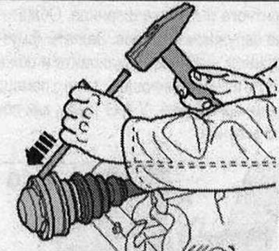
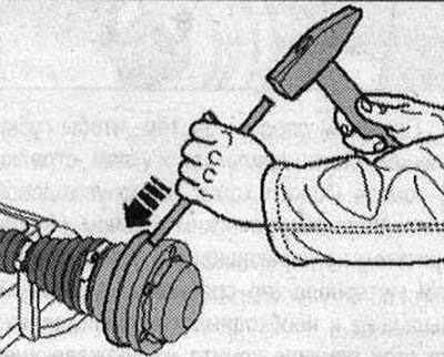
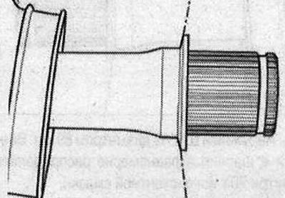
Knock off the cap using a copper or brass mandrel. Loosen and remove only the "small" clamp of the CV joint protective boot.
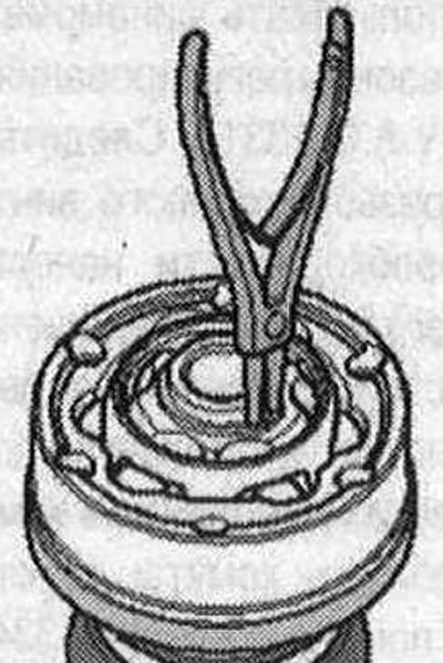
Remove the lock ring.
Press the inner CV joint away from the drive shaft using the tools shown in the figure.
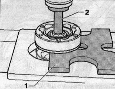
- 1. Thrust plate "VW 401" or thrust plate "VW 402"
- 2. Mandrel "VW 408 A"
If there is a disc spring, remove it from the shaft. Remove the joint boot from the drive shaft.
Installing an inner CV joint with a diameter of 100 mm or 107 mm: Slide the protective CV joint boot with the "small" clamp onto the drive shaft.
If present, properly install the disc spring onto the drive shaft.
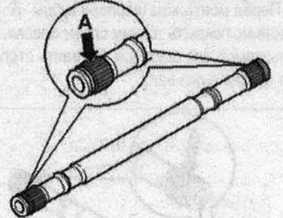
Before installing the hinge, the teeth "A" must be coated with a thin layer of grease used for the hinge.
Clamp the drive shaft in a vice with protective jaw pads. Carefully install the joint on the profiled shaft and press it in using the "VW 522" thrust sleeve and a hammer until it stops.
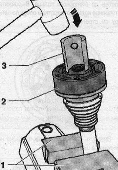
- 1. Protective jaw pads
- 2. Inner CV joint
- 3. Support sleeve "VW 522"
If present, the chamfer on the inner surface of the hub (splines) should face the thrust shoulder of the drive shaft. Install a new retaining ring. Check that the retaining ring is positioned correctly. Before installing the joint boot, apply half of the drive shaft grease included in the kit into the joint from the boot side. Degrease the adjacent surface of the cover.
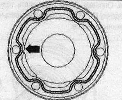
For inner CV joint with diameter 100 mm: Sealant (indicated by shading in the figure) apply to the clean surface of the inner side of the joint boot cap. Apply a continuous layer of sealant 2-3 mm thick. Apply a layer of sealant along the inner side of the "arrow" near the holes. Use sealant for this.
All
The protective cover and the surface of the cap must be degreased! Align the cap with the "arrow" bolts relative to the bolt holes.
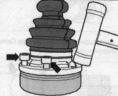
It is necessary to align it very precisely, since after fitting the cover it will be impossible to align it. Hammer the cover into place with a plastic hammer. Remove any protruding sealant immediately. Inject the remaining grease for drive shafts into the CV joint through the grooves for the balls.
For an internal CV joint with a diameter of 100 mm: Degrease the mating surface of the cover and the CV joint. Install a new seal on the cleaned glued surface of the CV joint "arrow".
For an internal CV joint with a diameter of 107 mm: Degrease the mating surface of the cover and the CV joint. Apply the sealant - the shaded area - to the clean surface of the inner side of the cover. Apply a continuous layer of sealant 2-3 mm thick. Next to the holes, apply a layer of sealant along the inner side "arrow". Use a sealant for this.
All
Align the cover with the bolts with the "arrows" relative to the holes for the bolts. It is necessary to align very precisely, since after the cover is mounted it will be impossible to align it. Hammer the cover into place with a plastic hammer.
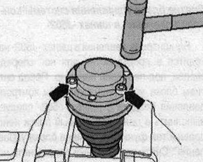
Remove any protruding sealant immediately. There should be no grease on the joint boot and drive shaft. Install the joint boot between the "arrows" in the groove "2".
- 1. Do not take into account.
- 2. Centering groove, push the joint boot so that it is fixed in the groove.
Ensure that the boot is correctly positioned on the hinge.
Crimp the clamp on the inner hinge: When installing a large clamp, make sure the locking pin is positioned between the two holes. Install and crimp stainless steel clamps using crimping pliers "V.A.G 1682", as shown in the figure.
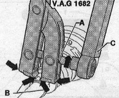
Set the pliers "V.A.G 1682", as shown in the figure. At the same time, make sure that the jaws of the pliers fit tightly to the corners of the "arrow B" of the clamp. Tighten the clamp by turning the lead screw with a torque wrench "C" (do not tilt the pliers). Due to the rigidity of the material (compared to rubber) boot and the need to use a stainless steel clamp for this reason, it can only be crimped with crimping pliers "V.A.G 1682". Tightening torque: 20 Nm. Use a torque wrench with an adjustment range of 5...50 Nm (e.g "V.A.G 1331"). Check the ease of movement of the lead screw thread of the pliers "A". If necessary, apply MoS2 grease. If rotation is difficult, for example due to contamination of the thread, the required clamping force is not achieved at the specified tightening torque. Install and crimp the clamps with locking tongues using pliers "3340", as shown in the figure.
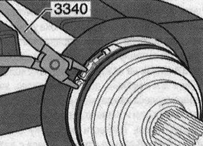
Secure the clamp to the first tongue by hand. Squeeze the clamp using pliers "3340".
Checking the outer CV joint
The outer CV joint with a cap cannot be disassembled. Only a visual inspection of the outer CV joint with a cap is possible. The grease remaining in the joint should not contain water or dirt. If a visual inspection reveals signs of wear or damage to the working surfaces of the balls, the outer CV joint with a cap must be replaced as an assembly. The amount and type of grease for the drive shaft with an outer CV joint with a diameter of 88 mm or 100 mm.
Checking the inner CV joint
The joint must be disassembled to replace the lubricant if it is heavily contaminated, and to inspect the surfaces that contact the balls for wear and pitting.
(The original article is available on the website: AUDIMANUAL)