
Remove the joint and joint boot. Remove the retaining ring "1".
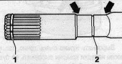
Installing an outer CV joint with a diameter of 89 mm or 94 mm: Install the joint boot with a new clamp on the drive shaft. There should be no grease on the joint boot and the drive shaft. Install the joint boot between the "arrows" in the groove "2".
- 1. Always replace the retaining ring (lock ring).
- 2. Centering groove, push the joint boot so that it is fixed in the groove.
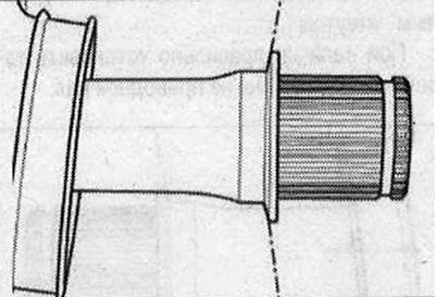
If present, properly install the disc spring onto the drive shaft.
Outer CV joint with a diameter of 89 mm: Insert into the joint and evenly distribute 70 g of consistent grease inside.
Outer CV joint with a diameter of 94 mm: Insert into the joint and evenly distribute 80 g of consistent grease inside.
All
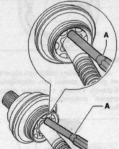
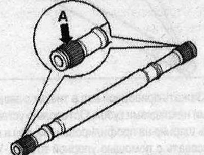
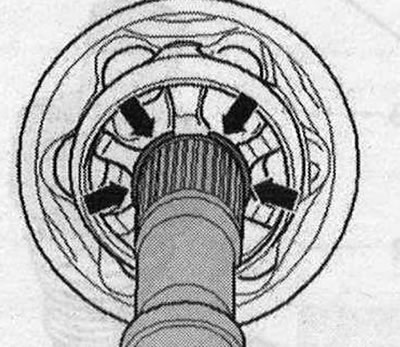
Before installing the joint, the teeth "A" must be coated with a thin layer of grease used for the joint. Insert the retaining ring into the groove of the shaft.
Slide the constant velocity joint up to the retaining ring. Align the retaining ring with the hole facing up and in the center "see arrows".
Screw the old bolt into the hinge as shown in the picture.
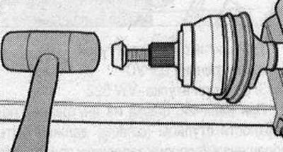
Tap the joint onto the drive shaft with a plastic hammer until the locking ring snaps into place. Install the boot onto the steel cap. Release air from the protective boot of the joint. Press the clamp onto the outer joint. Press the clamp onto the outer joint. Install and press the stainless steel clamps using crimping pliers "V.A.G 1682", as shown in the figure.
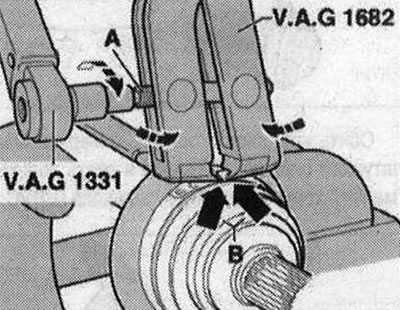
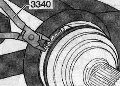
In doing so, make sure that the jaws of the pliers fit tightly against the corners of the "arrow B" of the clamp. Tighten the clamp by turning the lead screw with a torque wrench (do not tilt the pliers). Due to the rigidity of the material (compared to rubber) boot and the need to use a stainless steel clamp for this reason, it can only be crimped with crimping pliers "V.A.G 1682". Tightening torque: 20 Nm. Use a torque wrench with an adjustment range of 5...50 Nm (e.g "V.A.G 1331"). Check the ease of movement of the lead screw thread of pliers "A". If necessary, apply MoS2 grease. If rotation is difficult, for example due to contamination of the thread, the required clamping force is not achieved at the specified tightening torque. Install and crimp the clamps with locking tongues using pliers "3340", as shown in the figure. Fasten the clamp to the first tongue by hand. Squeeze the clamp using pliers "3340".
(This article was copied from the website AudiManual.ru)