
Table of contents: Installation ↓ Parts and assemblies of the drive… ↓ Volumes and types of lubricant ↓
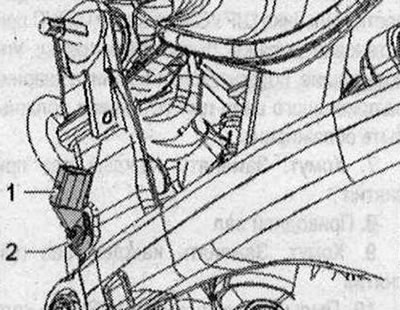
Loosen the bolts securing the drive shaft to the wheel hub. Remove the wheel. Remove the coil spring. Remove the exhaust system resonator. Remove the rear main gear. Remove the rear speed sensor "1". To do this, unscrew bolt "2". Remove the drive shafts inward.
Installation
Installation in reverse order. In this case, it is necessary to take into account the tightening torques. Install the rear main gear. Remove the end silencer of the exhaust system. Install the coil spring. Install the rear speed sensor. Tighten the wheel. Tighten the drive shaft to the wheel hub bolts.
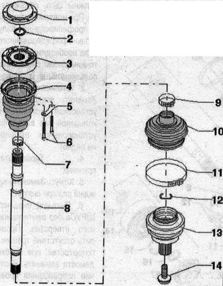
Parts and assemblies of the drive shaft with an outer CV joint with a diameter of 88 mm and an inner CV joint with a diameter of 100 mm
I 1. Bolt 200 Nm + turn 180°; Replace each time when removed. Observe installation instructions when loosening and tightening; 2. Outer CV joint. Outer diameter: 89 mm. Can only be replaced as an assembly. Install: use a plastic hammer to push onto the shaft until the locking ring springs back. When installing, insert the locking ring into the chamfer of the joint; use pliers if necessary. The sealing surfaces of the CV joint boot/outer CV joint must be degreased during installation. When mounting the joint on a profiled shaft, the teeth of the profiled shaft must be coated with a thin layer of grease used for the joint; 3. Retaining ring. Always replace. Insert into the shaft ring groove before installation (when the hinge is installed it is not visible); 4. Disc spring; 5. Clamp. Replace each time it is removed; 6. Outer CV joint boot without ventilation hole. Check for cracks and abrasions, replace if necessary. In case of damage, check the outer CV joint. The sealing surfaces of the CV joint boot/outer CV joint must be degreased during installation. The sealing surfaces of the joint boot/drive shaft must be degreased during installation; 7. Clamp. Replace each time it is removed; 8. Drive shaft; 9. Clamp. Replace each time it is removed; 10. Inner CV joint boot with cap without ventilation hole. Carefully remove the cap using a drift, replace if damaged. Inspect the inner CV joint if damaged. The sealing surfaces of the joint boot/CV joint must be degreased during installation. The sealing surfaces of the joint boot/drive shaft must be degreased during installation. Apply sealant to the mating surface before installing on the CV joint. Align the cap relative to the screw holes; 11. Backing plate; 12. Bolt. M 8.20 Nm + turn 90°. Replace each time when removing; 13. Disc spring; 14. Internal joint. Outer diameter: 100 mm. It can only be replaced when assembled. Taped surfaces the cover / inner joint and the protective cover of the joint/joint must be degreased before installation. When mounting the joint on a profiled shaft, the teeth of the profiled shaft must be coated with a thin layer of grease used for the joint; 15. Seal. Replace each time when removed. The glued surface of the CV joint must be degreased!; 16. Retaining ring. Replace each time when removed; 17. Cover. Carefully remove the cover using a mandrel; replace if damaged. The sealing surfaces of the CV joint boot must be degreased during installation. Align the cover relative to the screw holes
Volumes and types of lubricant
When replacing the boot, re-lubricate the joint. Grease to fill the joint. Use different types of grease for the outer and inner joints.
| External hinge | Lubricant Volume Total Volume | From this to the Hinge | From this into a corrugated case | |
| [mm] | [G] | [G] | [G] | |
| 89 | 70 | Distribute the grease evenly in the joint | ||
| Inner hinge | ||||
| 100 | 110 | Distribute the grease evenly in the joint, approximately half of the total volume on each side | ||
| External hinge | Lubricant Volume Total Volume | From this to the Hinge | From this into a corrugated case | |
| [mm] | [G] | [G] | [G] | |
| 94 | 80 | Distribute the grease evenly in the joint | ||
| Inner hinge | ||||
| 107 | 120 | Fill the joint with grease through the ball grooves | ||
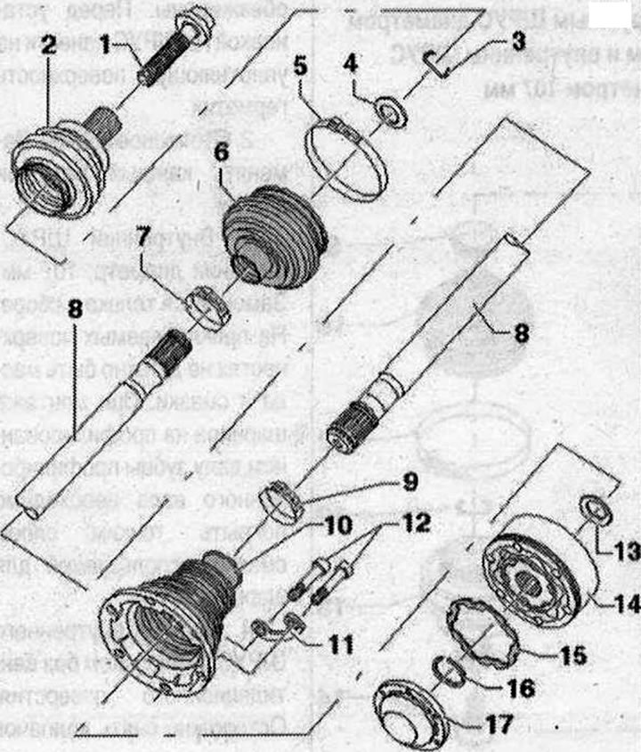
Parts and assemblies of the drive shaft with an outer CV joint with a diameter of 94 mm and an inner CV joint with a diameter of 107 mm
1. Cover. Carefully remove the cover using a mandrel, replace if damaged. The surfaces to be glued cover/inner CV joint must be degreased before installation. Apply sealant to the sealing surface before installation on the CV joint; 2. Retaining ring. Replace each time when removed; 3. Inner CV joint. Outer diameter: 107 mm. Replaceable only as a set. There should be no oil or grease on the surfaces to be glued. When mounting the joint on a profiled shaft, the teeth of the profiled shaft must be coated with a thin layer of grease used for the joint; 4. Inner CV joint boot with cap without ventilation hole. Carefully remove the cap using a drift, replace if damaged. If damaged, check the inner CV joint. The sealing surfaces of the cap/CV joint must be degreased during installation; 5. Backing plate; 6. Bolt. M10. 70 Nm. Replace each time when removing.; 7. Clamp. Replace each time it is removed; 8. Drive shaft; 9. Clamp. Replace each time it is removed; 10. Outer CV joint boot without ventilation hole. Check for cracks and abrasions, replace if necessary. In case of damage, check the outer CV joint. The sealing surfaces of the joint boot/outer steel cap must be degreased during installation. The sealing surfaces of the joint boot/drive shaft must be degreased during installation; 11. Clamp. Replace each time it is removed; 12. Retaining ring. Always replace. Install into shaft ring groove before installation (when the hinge is assembled it is not visible). Before installing the constant velocity joint, align the retaining ring with the center of the hole by moving it upwards; 13. Outer CV joint. Outer diameter: 94 mm. Can only be replaced as an assembly. Install: use a plastic hammer to push onto the shaft until the locking ring springs back. When installing, insert the locking ring into the chamfer of the joint; use pliers if necessary. The sealing surfaces of the CV joint boot/outer CV joint must be degreased during installation. When mounting the joint on a profiled shaft, the teeth of the profiled shaft must be coated with a thin layer of grease used for the joint; 14. Bolt. 200 Nm + turn 180°. Replace each time when removing; Observe the installation instructions when loosening and tightening. When replacing the boot, re-lubricate the joint
(The original text is available on the website Audimanual.ru)