
The use of an electronic engine management system has the following advantages:
- due to the optimal supply of fuel to the engine in all operating modes, fuel consumption is reduced while maintaining the dynamic characteristics of the vehicle;
- due to more complete combustion of fuel, as well as the use of a catalyst, the emission of harmful substances along with exhaust gases is reduced;
- due to the fact that the electronic engine management system detects and records faults in its memory, troubleshooting and detection is significantly accelerated.
The engine control system control unit is a small, high-speed computer. The engine control system sets the optimal ignition timing, moment, and amount of fuel supplied to the engine in all operating modes. The engine control system also interacts with other vehicle systems, in particular, with the automatic transmission control system or the anti-theft system.
The engine management system components are very reliable and require virtually no maintenance. Maintenance only requires replacing the air filter and spark plugs. Since complex, expensive equipment is required to check, adjust, and repair the engine management system, this work must be performed at a service station.
No adjustment of idle speed and CO level is required as part of preventive maintenance/inspection of the vehicle.
Safety note: The fuel system is under pressure. Before disconnecting the fuel lines, relieve the pressure in the fuel system. To do this, cover the connection with a rag and, being careful, disconnect. When disconnecting the system components, fuel may splash, so use glasses to protect your eyes from fuel getting into them.
To avoid injury and/or damage to devices and components of the engine control system (ignition and fuel injection systems), please follow these rules:
- when the engine is running, do not touch or disconnect high-voltage wires;
- connect and disconnect the engine management system wires (injection and ignition), and also the wires of measuring instruments only when the ignition is off;
- people with pacemakers are not recommended to check or repair the engine management system
- when testing under pressure, fuel must not be injected; to do this, follow the instructions given in the section "Testing under pressure".
Caution: When working on the fuel injection device, be sure to follow the general safety and hygiene rules, see chapter "Fuel system".
Functioning of the engine management system
Fuel from the fuel tank is supplied by an electric fuel pump through a fuel filter located on the bottom of the car to the fuel injectors. The fuel pressure regulator maintains constant pressure in the fuel system.
Electronically controlled injectors inject fuel into the intake ports just before the engine's intake valves. The engine control unit controls the fuel injector by varying the pulse width, or the length of time the injector is open, to provide a richer or leaner fuel mixture.
The air needed to burn the fuel passes through the air filter, air flow meter and throttle valve to the cylinder intake ports.
The volume of air entering the engine determines the amount of fuel required for complete combustion. The air flow meter is a energized tape conductor. A constant tape temperature is maintained by an electric current that varies depending on the mass of the air passing through. The current that must be supplied to maintain a constant tape temperature is proportional to the mass of the air flow. Based on information from the air flow meter and other sensors, the control unit adjusts the time and amount of fuel injected according to the measured amount of air and the engine speed. The longer the injector is open, the more fuel is injected.
Information received from various sensors (sensors) and commands sent to the actuators ensure optimal engine operation under all operating conditions. If important sensors fail, the control unit switches to the emergency driving program to avoid engine damage and be able to continue driving. Failure of the sensors will not necessarily be accompanied by a noticeable deterioration in engine performance, but after a while, during the next exhaust gas check, it will be noted when the engine management system failure memory is queried.
The throttle valve switch is located in the throttle assembly. The switch transmits a signal to the control unit about the position of the throttle valve at idle speed. The control unit opens or closes the throttle valve via a servomotor and thus maintains a stable idle speed.
The coolant temperature and engine air temperature sensors report the current temperature value via their electrical resistance. As the temperature increases, the sensor resistance decreases.
The ventilation and fuel vapor recovery system consists of an activated carbon filter and a magnetic valve. The activated carbon filter prevents harmful fuel vapors from entering the atmosphere from the fuel tank. Fuel that evaporates when heated is collected in a container with activated carbon. When the engine is running, fuel vapors are taken from the container and sent to the engine for combustion.
The lambda sensor measures the oxygen content in the exhaust gas flow. The control unit uses its signal to maintain the content of harmful emissions in the exhaust gases at the lowest level. In vehicles with a catalytic converter, the composition of the exhaust gases is maintained at a level that ensures the best afterburning in the catalytic converter.
The knock sensor is used to detect the onset of detonation in the engine cylinders and, based on this information, the engine control unit reduces the ignition timing. If there are ignition faults, the control unit shuts off the fuel supply to the corresponding cylinder.
Engines 1.8-I/125 hp and 2.4-/2.8-I-V6. A variable-length intake manifold that changes the length of the air path entering the cylinders depending on the engine operating conditions. A pneumatic rotary valve is used for this purpose. At low engine speeds, the air enters via a longer path and, due to the resonance effect, the engine cylinders are filled more completely, resulting in increased torque. At high speeds, the air path is shortened to more fully utilize the engine's power potential.
Engines 1.8-I/125 hp and 2.4-/2.8-I-V6. The device for turning the camshaft controlling the intake valves depending on the engine speed ensures the change of valve timing. When turning the camshaft to the "spat/lag" position, the smoothness of the engine running is improved at idle speed; accordingly, at high speeds, engine power increases. At low and medium speeds, with earlier closing of the intake valves, the filling of the cylinders is improved, and thus the torque characteristics are improved.
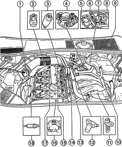
Fig. 4B.1. Location of the MOTRONIC engine management system components in the engine compartment with a 1.8-I/125 hp engine.
1 - air flow meter,
2 - coolant temperature sensor,
3 - camshaft position adjustment valve,
4 - throttle valve assembly,
5 - electrical connector of the lambda sensor,
6 - electrical connector of the crankshaft speed sensor,
7 - electrical connector of knock sensor 2,
8 - electrical connector of knock sensor 1,
9 - MOTRONIC engine control unit,
10 - air supply system channel switching valve,
11 - engine air temperature sensor,
12 - crankshaft speed sensor,
13 - knock sensor 2,
14 - knock sensor 1,
15 - fuel injectors,
16 - Hall sensor,
17 - ignition coils with switches,
18 - heated lambda sensor.
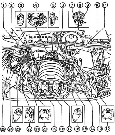
Fig. 4B.2. Location of the MOTRONIC engine management system components in the engine compartment with a 2.4-l engine
1 - electrical connector of heated lambda sensor 1,
2 - electrical connector of the knock sensor,
3 - coolant temperature sensor,
4 - MOTRONIC engine control unit,
5 - engine air temperature sensor,
6 - valve for switching channels of the air supply system,
7 - electrical connector of heated lambda sensor 2,
8 - electrical connector of the crankshaft speed sensor,
9 - electrical connector of knock sensor 2,
10 - MOTRONIC engine control unit,
11 - fuel pressure regulator,
12 - Hall sensor 2,
13 - lambda sensor,
14 - crankshaft speed sensor,
15 - knock sensor,
16 - valve 2 for switching channels of the air supply system,
17 - ignition coil with switch,
18 - knock sensor,
19 - fuel injectors,
20 - Hall sensor 1,
21 - lambda sensor 1,
22 - ground bus connection point,
23 - valve 1 for switching channels of the air supply system,
24 - air flow meter,
25 - Electromagnetic valve of the activated carbon tank.
[This article was previously published on the resource «AudiManual»]