
The right and left steering rod ends are structurally identical. They can be removed and installed without removing the steering gear.
Removal
Mark the position of the front wheels in relation to the hubs with paint. This is necessary for reinstalling the wheels in their original position, which maintains their balance. With the car standing on its wheels, loosen the front wheel mounting bolts. Raise the front of the car and secure it on stands, unscrew the bolts and remove the front wheels.
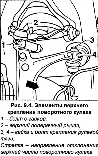
Unscrew bolt and nut 3 and 4 (Fig. 9.4) securing the steering rod end to the steering knuckle.
Unscrew the plastic nut 1 (Fig. 9.5).
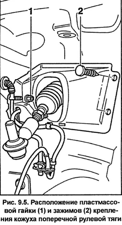
Using a small screwdriver, remove the two clamps 2 (Fig. 9.5).
Remove the tie rod cover.
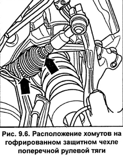
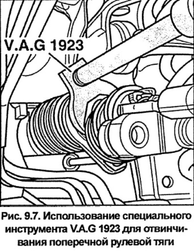
Loosen the clamps on the bellows protective boot of the transverse steering rod (see fig. 9.6). Move the corrugated protective cover as far out as possible and use the special tool VAG 1923 to unscrew the transverse steering rod (see fig. 9.7).
Remove the steering rod.
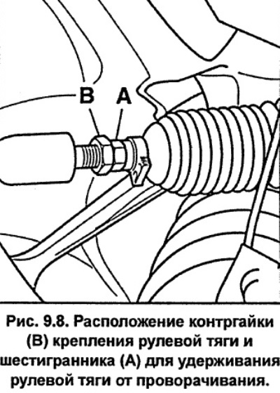
If necessary, loosen lock nut B (Fig. 9.8) and unscrew the tie rod end from the steering rod, holding the tie rod end by the hexagon A to prevent it from turning. Count the number of turns during unscrewing. Screw the new tie rod end into the steering rod by the same number of turns. Tighten the tie rod end lock nut to a torque of 40 Nm, holding the tie rod end by the hexagon to prevent it from turning (see fig. 9.8).
Installation
Check the condition and, if necessary, replace the tie rod or tie rod joint.
When installing a new steering rod, measure and, if necessary, adjust the length of the rod, while its length should be equal to the length of the removed steering rod.
Install the steering rod in place and screw it to the steering gear, tightening it to a torque of 100 Nm.
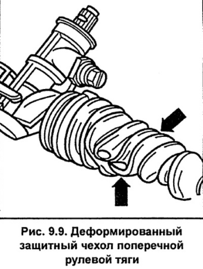
Install the steering gear protective bellows and secure it with new clamps. Make sure the boot is not deformed or twisted (see fig. 9.9).
Install the tie rod end onto the steering knuckle and tighten bolt 3 (Fig. 9.4) to 7 Nm. Screw on a new self-locking nut 4 (Fig. 9.4) and tighten it to 45 Nm.
Apply a thin layer of grease to the flange that centers the wheel disc. Install the wheel, aligning the previously applied marks, and secure it with bolts. Lower the car to the ground and tighten the wheel mounting bolts to a torque of 120 Nm.
Check and, if necessary, adjust the wheel alignment angles.
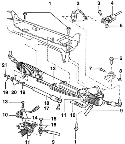
Fig. 9.3. Steering gear and steering rods
1 - bolts, 65 Nm,
2 - protective cover,
Check for cracks and replace if necessary.
3 - Torx bolt with eccentric T50,
To loosen, turn clockwise.
4 - steering shaft,
5 - self-locking nut, 30 Nm,
A new nut must be used during installation.
6 - bolt, 7 Nm,
7 - screw,
8 - self-locking nut, 45 Nm,
A new nut must be used during installation.
9 - return pipeline,
10 - pressure pipeline,
11 - cylindrical screw, 13 Nm,
12 - power steering,
13 - hollow bolt, 40 Nm,
With built-in check valve
14 - washers, 14x20,
15 - hollow bolt, 50 Nm,
16 - washers, 16x22,
17 - bolt, 35 Nm,
18 - shock absorber,
Not installed on all models.
19 - support,
20 - rubber gasket,
21 - nut, 10 Nm