
Table of contents: Removal ↓ Installation ↓
Faulty injectors can cause loud knocking in the engine, which usually suggests a bearing defect. In case of such malfunctions, start the engine and at idle speed, loosen the union nuts of the high-pressure fuel lines one by one. If the knocking disappears after loosening the next nut, then this is evidence of a faulty injector.
The injectors can also be checked using a special pressure gauge (in the workshop).
The first signs of injector malfunctions are:
- engine power loss;
- too much black smoke from the exhaust pipe;
- significant blue emissions when starting a cold engine;
- increased fuel consumption;
- engine overheating;
- knocking in one or more cylinders;
- misfires.
Removal
1. Clean the high pressure fuel lines from the outside with a cold cleaner.
2. Remove the high-pressure fuel lines. To do this, use a socket or spanner to unscrew the union nuts securing the lines.
Attention! Do not change the bend shape of the fuel lines. All high-pressure fuel lines must be removed as a complete set.
3. Disconnect the fuel return hoses from the injectors.
4. Remove the cylinder head cover.
5. Unscrew the bolts securing the fuel injector pressure plates (see arrows in the illustration) and unscrew the injectors themselves.
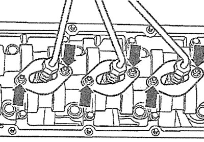
4.5. Unscrew the bolts securing the fuel injector pressure plates (see arrows) and unscrew the injectors yourself
6. Vehicles with manual transmission. Engage 4th gear if the camshaft lobe interferes with the injector removal. Move the vehicle to rotate the engine and displace the camshaft lobe away from the injector.
7. Cars with automatic transmission. Attach pressure plates to all injectors if one of the camshaft lobes interferes with the removal of the injector. Disconnect the multi-pin plug from the fuel injection pump. Turn on the starter so that the engine turns over and the cam does not interfere.
8. Operate the starter only after securing all injectors with plates and after disconnecting the multi-pin plug from the high-pressure fuel pump.
9. Remove the heat shield from the removed injector.
Installation
10. Be sure to install a new heat shield gasket between the cylinder head and the injector.
11. Install the nozzle back into place.
12. Secure the injector with the pressure plate. The tightening torque of the injector pressure plate nuts is 10 Nm.
13. Install the cylinder head cover and secure it with bolts to a tightening torque of 10 Nm.
14. Install the return fuel lines between the injectors.
15. Tighten the union nuts of the high-pressure fuel lines. The tightening torque is 30 Nm.
16. To remove the injector with the needle lift sensor (see illustration 4.0), which is installed in the third cylinder, follow these steps.
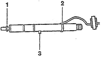
4.0. Fuel injector with needle lift sensor:
1 - heat-protective gasket
2 - bushing
3 - mounting pin(when installing, the pin must enter the corresponding groove in the cylinder head)
17. Disconnect brown connector 1 from the fuel injector needle lift sensor (see illustration).
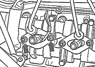
4.17. Disconnect brown connector 1 from the fuel injector needle lift sensor
18. Unscrew the bolts (see arrows in illustration 4.17) fuel injector pressure plate mounts and carefully remove the injector.