
Table of contents: Removal ↓ Installation ↓
Audi Allroad diesel cars are equipped with an intake manifold with variable intake tract length. For this purpose, flaps are installed in the intake manifold, which are actuated by a pneumatic valve. The extension of the intake manifold tract at low engine speeds ensures good cylinder filling and high torque. At high engine speeds, the intake manifold tract is closed by flaps and thus shortened in order to fully utilize the engine's potential.
Removal
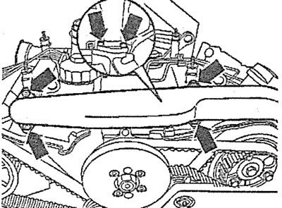
1. Press the latches and remove the air filter cover 2, and also remove the air intake 1 (see illustration).
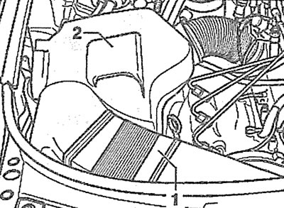
3.1. Press the clamps and remove the cover 2 of the air filter, and also remove the air intake 1
2. Remove the upper engine protective cover.
3. Remove the power steering fluid reservoir protective cover (see arrow in illustration).
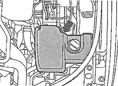
3.3. Remove the protective cover of the power steering reservoir (see arrow)
4. Cars with AFB, AKN engines. If possible, disconnect the low pressure hose 1 from the valve actuator nipple in the intake manifold (see illustration).
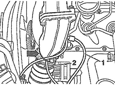
3.4. Disconnect the low pressure hose 1 from the valve connection of the flap actuator in the intake manifold. Cars with AFB, AKN engines
5. Cars with AFB, AKN engine. Disconnect the supply air duct from the intake manifold by loosening the clamp 2 (see illustration 3.4).
6. Vehicles with AFB, AKN engine. Disconnect the wiring harness (see arrow in illustration 3.4).
7. Cars with AKE, AYM, BAU, BCZ, BDG, BOH, BFC engines. Disconnect plug 2, and then disconnect the supply air duct by loosening clamp 1 (see illustration).
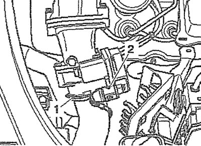
3.7. Disconnect plug 2, and then disconnect the supply air duct by loosening clamp 1. Cars with AKE, AYM, BAU, BCZ, BDG, BDH, BFC engines
8. Disconnect the fuel injection pump connector.
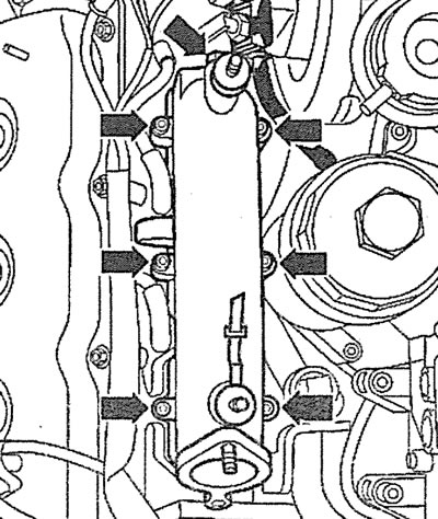
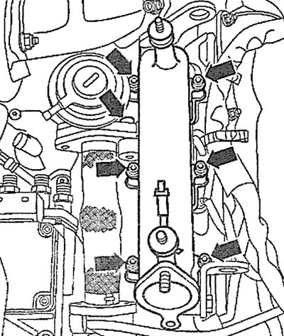
9. Unscrew the bolts (see arrows in the illustration) and remove the intake manifold pipe.
3.9. Unscrew the bolts (see arrows) and remove the intake manifold pipe
10. Disconnect the low pressure hoses from the boost air vacuum valve and the mechanical EGR valve (see arrows in the illustration).
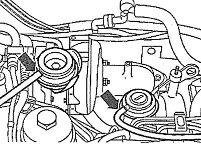
3.10. Disconnect the low pressure hoses from the boost air vacuum valve and the mechanical EGR valve (see arrows)
11. Left cylinder head. Unscrew the bolts (see arrows in the illustration) and remove the turbocharger heat shield.
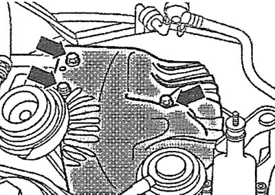
3.11. Unscrew the bolts (see arrows) and remove the turbocharger heat shield
12. Unscrew the union nuts and disconnect the high-pressure fuel lines of the fuel injectors, having first marked their installation position.
13. Release the wire harness from the holders and move it away from the work area.
14. Unscrew the mounting bolts (see arrows in illustrations 3.14 and 3.14a) and remove the intake manifold from the corresponding cylinder head.
3.14. Unscrew the mounting bolts (see arrows) and remove the intake manifold. Right cylinder head |
3.14a. Unscrew the mounting bolts (see arrows) and remove the intake manifold. Left cylinder head |
Installation
The intake manifold is installed in the reverse order of removal.
15. The tightening torque of the intake manifold mounting bolts is 10 Nm.
The original source of the article can be found on the website Audimanual.ru