
Table of contents: Gear shift lever mechanism,… ↓ Fastening the gearbox to the engine ↓ Manual transmission - housing,… ↓ Retaining rings ↓
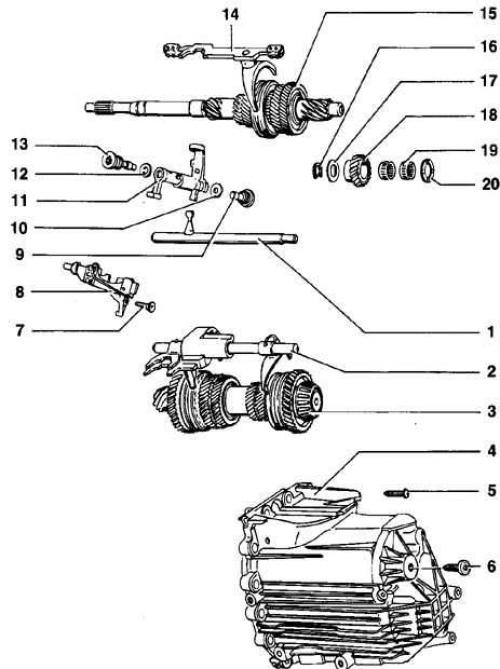
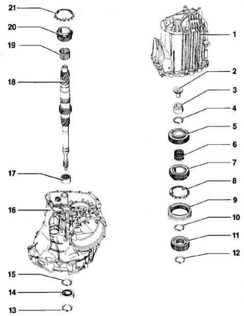
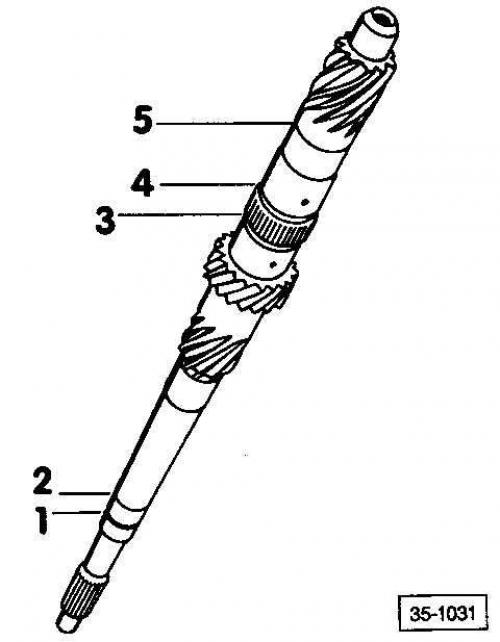
Gearbox 012 complete
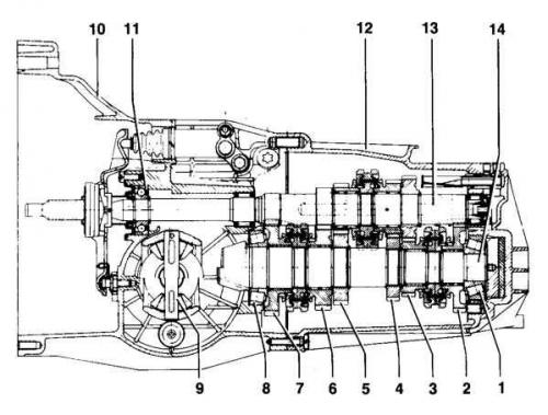
- 1. Tapered roller bearing
- 2. Reverse gear
- 3. 5th gear pinion
- 4. 4th gear pinion
- 5. 3rd gear pinion
- 6. 2nd gear pinion
- 7. 1st gear pinion
- 8. Tapered roller bearing
- 9. Differential
- 10. Clutch housing
- 11. Ball bearing
- 12. Gearbox housing
- 13. Drive shaft
- 14. Intermediate shaft gear block
Specifications, 5-speed gearbox 012
| Code |
AKL/AUF
|
ALP/AAD
|
|
4-cylinder
|
5-cylinder
| |
| Gear ratio: | ||
| - main gear |
37:9 = 4.111
|
37:10 = 3.700
|
| - first gear |
39:11 = 3.545
|
39:11 = 3.545
|
| - second gear |
40:19 = 2.105
|
40:19 = 2.105
|
| - third gear |
39:30 = 1.300
|
39:30 = 1.300
|
| - fourth gear |
33:35 = 0.943
|
35:34 = 1.029
|
| - fifth gear |
30:38 = 0.789
|
31:37 = 0.838
|
| - reverse gear |
35:10 = 3.500
|
35:10 = 3.500
|
| Speedometer |
electronic
| |
| Lubricant volume |
2.35 liters
| |
| Specification |
Transmission oil G 50 (synthetic)
| |
| SAE 75 W 90 | ||
| Clutch drive |
hydraulic
| |
| Clutch disc diameter |
210 mm
|
228 mm
|
| Drive shaft flange diameter |
100 mm
|
108 mm
|
| Speed in highest gear at 1000 rpm |
34 km/h
|
36 km/h
|
Warning: Do not lubricate the gear shift lever mechanism.
Gear shift lever mechanism, adjustment/check
Removal
1. Disconnect the negative battery cable.
2. Remove the three upper engine and gearbox mounting bolts.
3. Disconnect the transmission ground wire from the gearbox.
4. Remove the speedometer transmitter connector and the multifunction transmitter connector by squeezing the clamps.
5. Disconnect the catalytic converter connector.
6. Remove the gearbox housing protective plate.
7. Remove the exhaust manifold mounting bolts.
8. Remove the front exhaust pipe.
9. Remove the rear cross member.
10. Disconnect the automatic seat belt tensioner cables from the transmission.
11. Remove the gear shift rod.
12. Remove the clutch housing protective plate.
13. Remove the drive shaft protective plate.
14. Disconnect the axle shafts from the gearbox.
15. Turn the steering wheel all the way to the right and secure the axle shafts by tying them to the body.
16. Remove the clutch slave cylinder.
17. Remove the steering gear bracket.
18. Mount the engine on the support.
19. Install the gearbox on the support
20. Remove the fastener on the rear left side of the gearbox.
21. Remove the front engine mount.
22. Remove the lower transmission and engine mounting bolts.
23. Slowly lower the gearbox.
Installation
Installation is carried out in the reverse order of removal.
Please note the following when installing:
- check that the centering bushings are installed correctly.
- install the clutch slave cylinder into place using a lever so that the bolt can be inserted easily.
Caution: The clutch slave cylinder mounting bolt has a pointed end to facilitate installation.
Tightening torques for threaded connections
| Fastening the gearbox to the engine: | |
| – M8 bolts |
25 Nm
|
| – M10 bolts |
45 Nm
|
| – M12 bolts |
65 Nm
|
| Fastening the drive shaft to the flange: | |
| – M8 |
45 Nm
|
| – M10 |
80 Nm
|
Fastening the gearbox to the engine
4-cylinder engine
- 1 = bolt M12 x 70
- 2 = bolt M12 x 85
- 3 = bolt M12 x 100
- 4 = bolt M8 x 15
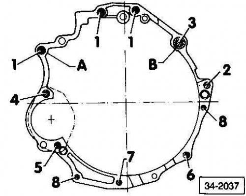
5-cylinder engine
- 1 = bolt M12 x 70
- 2 = bolt M12 x 80
- 3 = bolt M12 x 90
- 4 = bolt M12 x 100
- 5 = bolt M11 x 120
- 6 = bolt M10 x 50
- 7 = bolt M10 x 40
- 8 = bolt M8 x 40
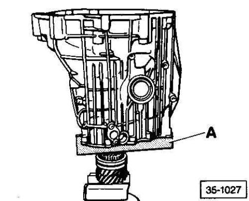
Location of centering bushings: points A and B
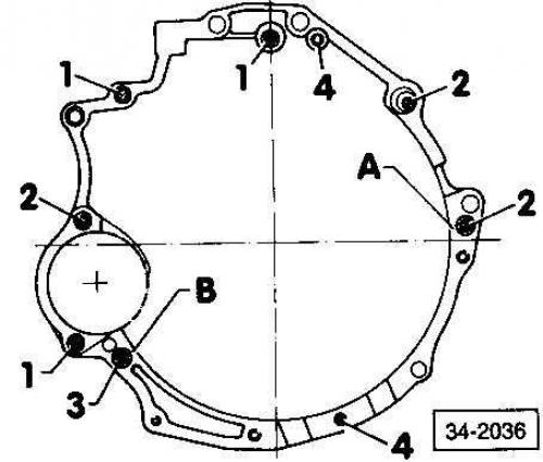
Location of centering bushings: points A and B
Warning: If you need to replace the final drive housing or the pinion or hollow shaft tapered roller bearing and the r deviation is not marked on the bevel gear, the pinion installation position must be determined before removing the transmission housing (it is necessary to carry out measurements of the actual magnitude of the deviation).
Warning: Before installing the transmission case, check that the guide bushings are installed in the transmission case.
Warning: Handle the speedometer transmitter with care. Do not drop it, otherwise the speedometer reading may not be accurate.
Main gear mechanism
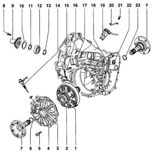
- 1. Speedometer drive
- 2. Differential
- 3. Sealing ring
- 4. Main gear cover
- 5. Socket head bolt - 25 Nm
- 6. Retaining ring
- 7. Drive shaft flange
- 8. Socket head bolt - 35 Nm
- 9. Guide bushing with sealing ring
- 10. Concave washer
- 11. Retaining ring
- 12. Ball bearing of the drive shaft
- 13. Retaining ring
- 14. Speedometer transmitter
- 15. Main gear housing
- 16. Socket head bolt - 10 Nm
- 17. Connector for connecting a multifunctional transmitting device
- 18. Gear shift lever channel cover
- 19. Multifunctional transmitting device
- 20. Locking film for multifunctional transmitting device
- 21. Bolt 25 Nm
- 22. 5th gear and reverse gear lock
- 23. Retaining ring
Warning: The speedometer drive1 can be replaced without removing the gearbox.
Warning: Differential 2 can be removed without removing the transmission housing.
Warning: Remove sealing ring 3 using tool VW 681.
Warning: Seal final drive cover 4 using sealant AMV 188 200 03.
Warning: Always replace retaining rings 6 and 23.
Warning: Install the drive shaft flange using the VW 295 tool.
Warning: The side of the concave washer 10 with the smaller diameter faces the guide bushing (concave side).
Warning: Mark retaining rings 11, 13 after removal.
Warning: Drive shaft flange sealing ring - remove with VW 681 tool and install (5 mm below the surface of the main gear housing) using the VW 195 tool.
Warning: Final drive housing 15: Input shaft flange sealing ring - remove with VW 681 tool. Install (5 mm below the surface of the main gear housing) using tool VW 195. 3rd/4th gear shift rod bushing – install using tools VW 295 and VW 295A. Seal with sealant AMV 188 200 03.
Warning: Gearshift lever channel cover 18 - tighten the mounting bolt to 20 Nm
Warning: The 5th gear and reverse gear lock 22 can be replaced without removing the gearbox. The beveled side of the plastic sleeve faces the shift shaft. Tightening torque of the mounting bolts: 10 Nm.
Drive shaft mechanism
- 1. Inner shift rod
- 2. 1st, 2nd, 5th gear shift rod and reverse gear with shift fork
- 3. Leading gear with hollow shaft
- 4. Gearbox housing
- 5. Socket head bolt - 25 Nm.
- 6. Socket head bolt for reverse gear axle - 35 Nm
- 7. Socket head bolt - 25 Nm
- 8. Castle
- 9. Socket head bolt - 40 Nm
- 10. Washer
- 11. Shift shaft
- 12. Washer
- 13. Socket head bolt
- 14. 3rd/4th gear shift rod and shift fork
- 15. Drive shaft
- 16. Retaining ring
- 17. Washer
- 18. Reverse gear pinion
- 19. Needle bearing of the driven gear of the reverse gear
- 20. Thrust washer
Warning: Remove the sealing ring of the inner shift rod 1 with the VW 681 tool and install it flush with the VW 460/2 tool. With the gearbox installed, carefully remove the sealing ring with a screwdriver and install it with the VW 423 tool. First remove the exhaust pipes and the shift rod to create space.
Warning: 1st, 2nd, 5th and reverse gear shift rod with shift fork 2 – for disassembly/ assembly, remove / install the spring pins. The 1st / 2nd gear shift forks can be replaced separately. Replace the 5th gear/ reverse gear shift fork only together with the shift ring and shift rod.
Warning: Reverse gear shaft socket head bolt 6 – 35 Nm. The reverse gear shaft does not need to be removed to remove the reverse gear pinion.
Warning: Socket head bolt 7-25 Nm. The inside of the head faces the spring/lock safety mechanism.
Warning: Install lock 8 after installing shift shaft 11 and inner shift rod.
Warning: 3rd/4th gear shift rod and shift fork: The shift rod or shift fork can be replaced separately. Replace the shift rod bearing if it is worn.
Removal the shift shaft bolts
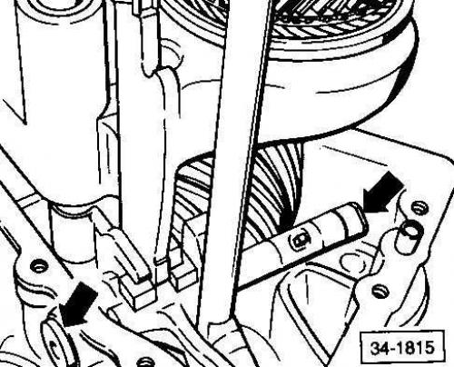
The arrows indicate the shift shaft bolts.
Position of the gear shift mechanism
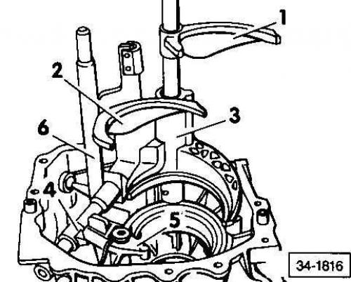
1. 5th gear/reverse gear shift rod with shift fork
2. 3rd/4th gear shift rod
3. 1st/2nd gear shift fork
4. Shift shaft
5. Castle
6. Inner shift rod
Position of the drive shaft, drive pinion with hollow shaft, shift rods and shift forks
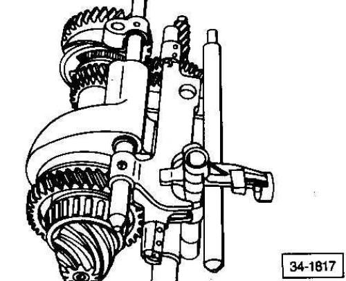
These elements must be installed together.
The shift shaft and inner shift rod can be installed later.
Installing the shift shaft and inner shift rod
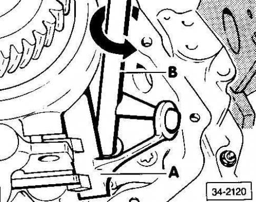
- A - switching shaft
- B - internal shift rod
Execution order
1. Shift into 3rd gear.
2. Install the shift shaft.
3. Place the inner shift rod B sideways on the hole in the final drive housing and align it with the bracket socket on the shift shaft.
4. Turn the shift rod inward in the direction of the arrow (see Fig. Installing the shift shaft and inner shift rod).
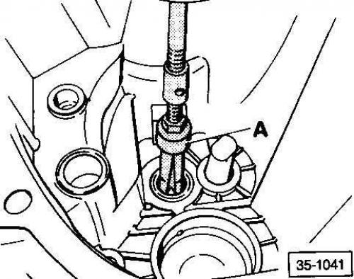
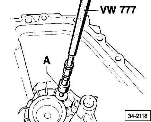
Removal the shift rod bushing
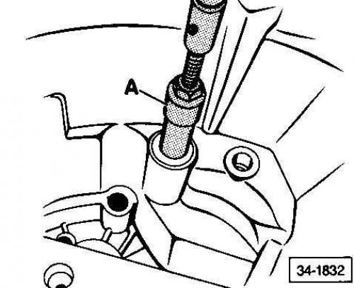
Use a hammer and an internal puller A of 18.5-23.5 mm (for example, 1088 or Kukko 21/3).
Removal and installation the shift fork bearing
Removal and installation the oil pan
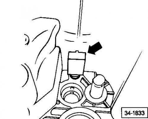
- The arrow indicates the oil collector
Execution order
1. Remove the oil pan using a screwdriver.
2. insert the oil pan deep enough into the transmission case that the oil pan retaining tabs engage the slots in the transmission case.
3. The oil pan cup should face up in the transmission housing.
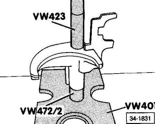
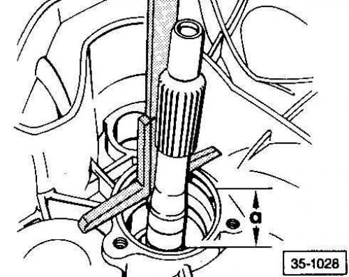
Installing the inner shift rod seal ring
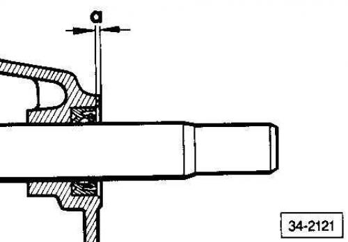
a = 1 mm
Manual transmission - housing, gears, shafts
Drive shaft assembly
- 1. Gearbox housing
- 2. Plastic sleeve
- 3. Needle bearing - drive shaft
- 4. Retaining ring
- 5. 5th gear pinion
- 6. Needle bearing - 4th gear
- 7. 4th gear pinion
- 8. Synchronizer ring
- 9. Sliding clutch - 3rd/4th gear
- 10. Retaining ring
- 11. Synchronizer hub - 3rd/4th gear
- 12. Retaining ring
- 13. Retaining ring
- 14. Ball bearing - drive shaft
- 15. Retaining ring
- 16. Main gear housing
- 17. Needle bearing - drive shaft
- 18. Drive shaft
- 19. Needle bearing - 3rd gear
- 20. 3rd gear pinion
- 21. Synchronizer ring - 3rd gear
Warning: Always replace plastic bushing 2. It is missing from the drive shaft, which does not have lubrication holes for 3rd/4th gear.
Warning: Needle bearing 2 is damaged when removed. Always replace it. Install it with the VW 416B tool to a depth of 214 mm, measured from the surface of the crankcase.
Warning: Snap ring 4 - check the required thickness when replacing the 5th gear.
Warning: Retaining ring 10 - check the required thickness when replacing the synchronizer hub.
Warning: Synchronizer hub 11 - protruding rim faces 3rd gear driven gear.
Warning: Snap Ring 13 - If you are going to use the old ball bearing and shaft, you should measure the thickness of the old snap ring and replace it with a new one of the same thickness.
Warning: Snap Ring 15 - If you are going to use the old ball bearing and shaft, you should measure the thickness of the old snap ring and replace it with a new one of the same thickness
Warning: Needle Bearing - Drive Shaft. Install with Tool 40-202.
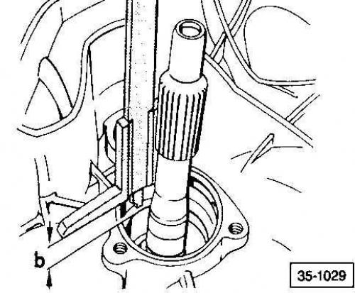
Removal the drive shaft needle bearing
Needle bearing installation depth
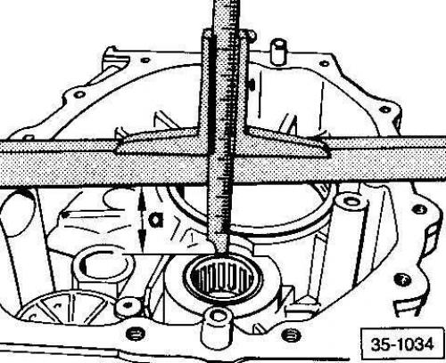
a = 39.5 mm
The installation depth is measured from the lower edge of the check ruler to the upper edge of the bearing.
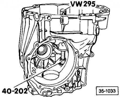
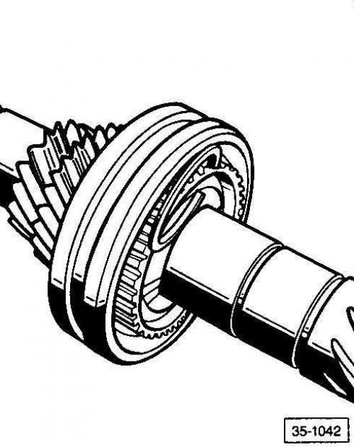
Installing a ball bearing into the crankcase
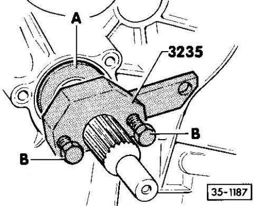
Execution order
1. Install the retaining ring onto the drive shaft.
2. Install the ball bearing onto the drive shaft until it stops.
3. Install the thrust pad of the 3235 release tool onto the ball bearing.
4. Install release tool 3235 behind the clutch disc splines on the input shaft.
5. Press on the ball bearing by tightening two bolts B, installed in the recesses of the thrust heel A.
6. Press the bearing until it stops, tightening the two bolts one by one and gradually.
Warning: Bolts B should be tightened alternately (for example, half a turn at a time), otherwise, the ball bearing may rotate and be damaged.
Warning: Ball bearing installation position: The open side of the plastic housing should face the guide sleeve.
Checking the synchronizer ring for wear
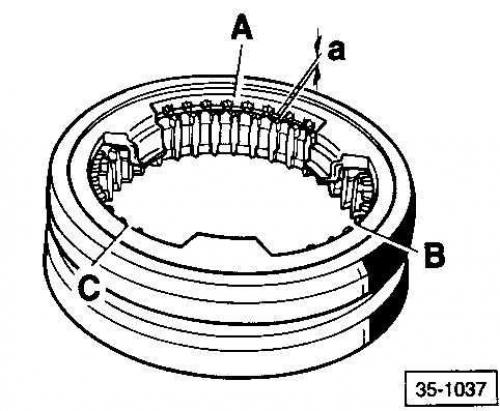
Execution order
1. Install the synchronizer ring on the sliding sleeve and measure the clearance a using a feeler gauge at points A, B and C.
2. Add the resulting values and divide the sum by 3.
3. The obtained value should not be less than 0.5 mm.
Installing the sliding clutch – 3rd/4th gear
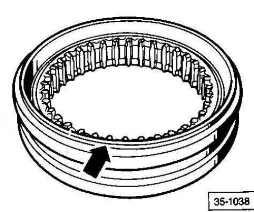
Side with groove (indicated by the arrow) facing the 3rd gear pinion.
Installing the synchronizer spring
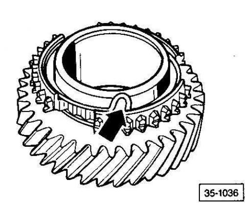
Install the spring (indicated by the arrow) into the gear, placing the pointed end of the spring into the groove.
Removal the 5th gear
A = removable device for 22–115 mm, e.g. Kukko 17/2.
Installing the 5th gear
The protruding edge faces the reverse gear. The lubrication channels face the 4th gear.
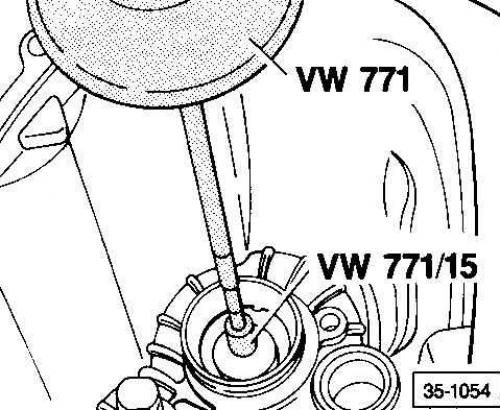
Removal/installing the drive shaft needle bearing
- A = 22-28 mm puller, e.g. Kukko 11/4
- B = VW 771 hammer
Warning: Before installing the bearing puller, split/remove the plastic sleeve if fitted. To install the bearing, press it in using the VW 416B drift to a depth of 214 mm, measured from the crankcase surface.
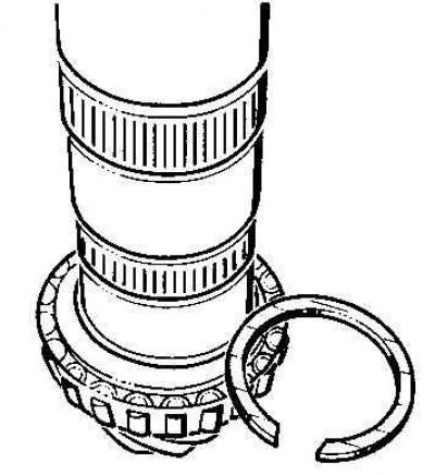
Retaining rings
Installing the 4th gear retaining ring
Determine the maximum possible thickness of the snap ring that can be installed and install it. The snap ring for the 5th gear is selected in the same way.
| Thickness of retaining ring, mm | Number |
| Retaining ring 3 (brown) | |
|
2.00
|
902 945.01
|
| Retaining ring 4 (blue) | |
|
1.90
|
902 944.01
|
|
1.93
|
902 944.02
|
|
1.96
|
902 944.03
|
|
1.99
|
902 944.04
|
|
2.02
|
902 944.05
|
|
2.05
|
902 944.06
|
| Retaining ring 5 | |
|
1.90
|
902 942.02
|
|
1.93
|
902 942.03
|
|
1.96
|
902 942.04
|
|
1.99
|
902 942.05
|
|
2.02
|
902 942.06
|
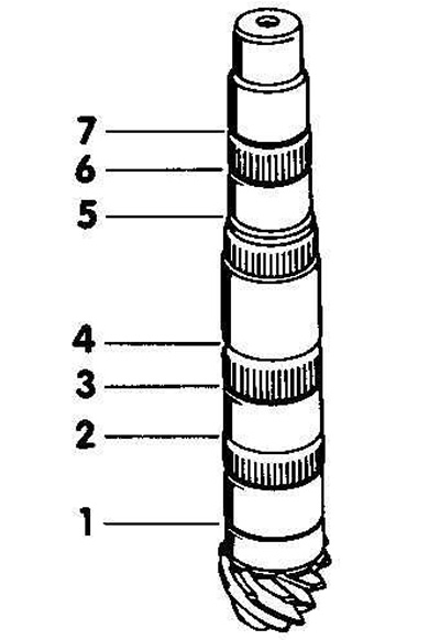
Installation location, selection of retaining rings
The retaining rings are shown in the figure and are numbered according to their position on the drive shaft.
Retaining rings 1, 2, 4 and 5 should be selected. The thickness of retaining ring 3 is always constant.
Determine the required thickness of retaining rings 1 and 2.
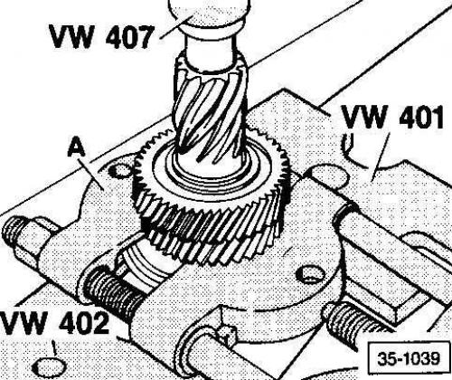
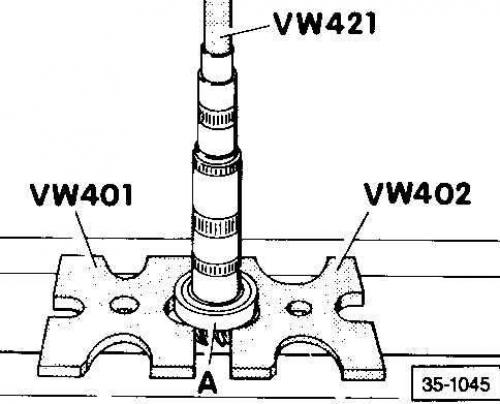
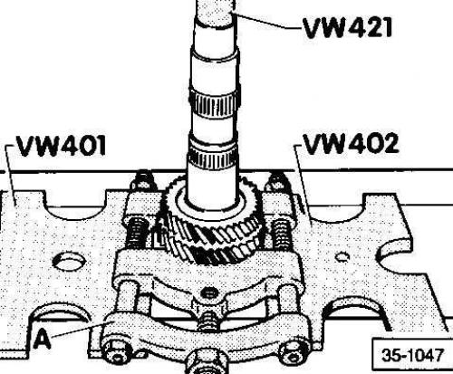
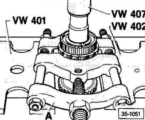
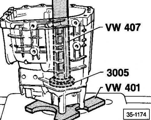
Removal the 3rd/4th gear synchronizer hub
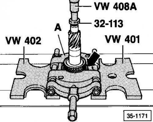
- VW 401/ VW 402 = stubborn heels
- 32–12 = disk
- VW 408A = punch
- A = puller 22–115 mm, type Kukko 17/2
Execution order
1. Install the following tools as shown in the figure. Before installing puller A, press the 3rd gear synchronizer ring (indicated by the arrow) to the 3rd gear.
2. Remove the synchronizer hub.
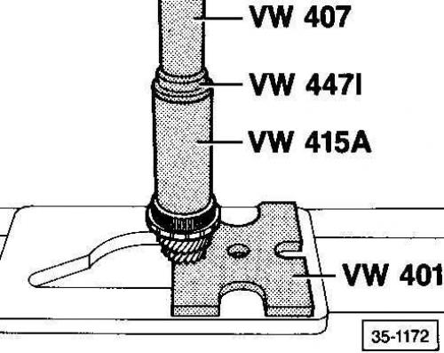
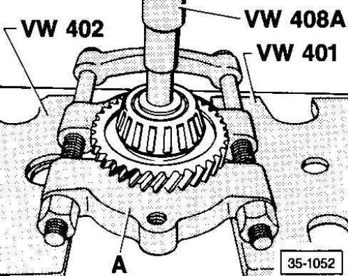
Installing the 3rd/4th gear synchronizer hub
Installing a plastic bushing
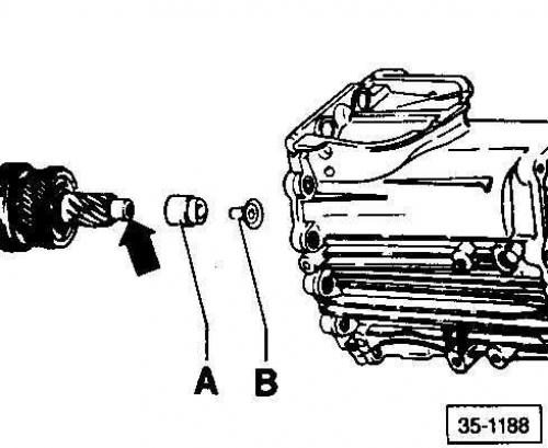
Install plastic bushing B together with needle bearing A.
Warning: Plastic bushing B is only installed on the drive shaft with lubrication grooves (indicated by an arrow) for 3rd/4th gear.
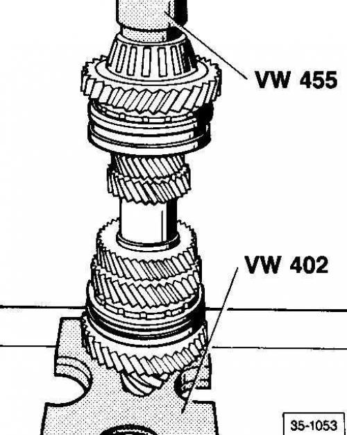
Adjusting the drive shaft
1. Secure the drive shaft in a vice with soft pads on the jaws
2. Install A, spacer plate 3167, to 3rd gear.
3. Install the crankcase onto the spacer plate, sliding it onto the drive gear.
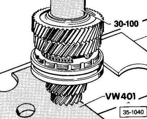
Installing the retaining ring
1. Install the depth gauge on the crankcase and measure the distance to the lower groove on the shaft. a = 28.5 mm.
2. Install the depth gauge on the crankcase and measure the distance to the ball bearing installation location. b = 26.8 mm.
3. Determine the required thickness of the lower retaining ring. Dimension x: x = a - b. x = 28.5 - 26.8 = 1.70 mm. Determine the required thickness of the retaining ring (See table 1).
4. Install the snap ring and ball bearing onto the shaft using a 30-100 mandrel.
5. Find the thickest retaining ring that will fit. See Table 2.
Table 1
| Size | Thickness | Number |
|
1.64 – 1.71
|
1.69
|
902 941.05
|
|
1.72 – 1.79
|
1.77
|
902 941.06
|
|
1.80 – 1.87
|
1.85
|
902 941.07
|
|
1.88 – 1.95
|
1.93
|
902 941.08
|
|
1.96 – 2.03
|
2.01
|
902 941.09
|
|
2.04 – 2.11
|
2.09
|
902 941.10
|
|
2.12 – 2.19
|
2.17
|
902 941.11
|
|
2.20 – 2.27
|
2.25
|
902 941.12
|
|
2.28 – 2.35
|
2.33
|
902 941.13
|
Table 2
| Thickness (mm) | Number |
|
1.69
|
902 941.05
|
|
1.77
|
902 941.06
|
|
1.85
|
902 941.07
|
|
1.93
|
902 941.08
|
|
2.01
|
902 941.09
|
|
2.09
|
902 941.10
|
|
2.17
|
902 941.11
|
|
2.25
|
902 941.12
|
|
2.33
|
902 941.13
|
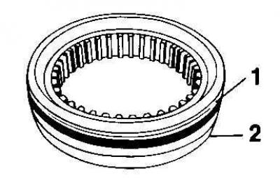
Removal the outer race of a double-row tapered roller bearing
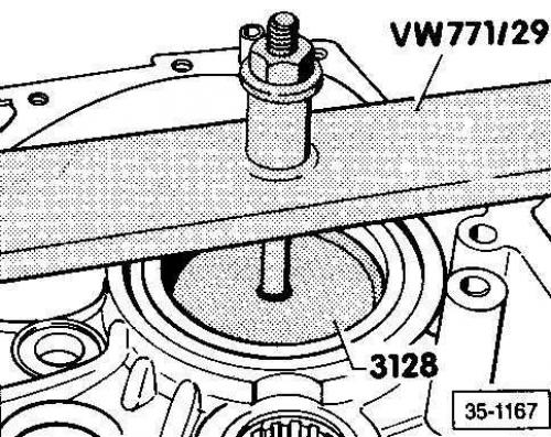
Installing the outer race of a double-row tapered roller bearing
1. Place the release plate of puller 3128 under the outer race.
2. install the VW 771/29 bar and install the bolt on the gearbox housing. When tightening the bolt, the outer race is removed from the housing.
Removal the inner race of a double-row tapered roller bearing
Caution: To remove the inner race, the outer race A must be installed.
Installing the inner race of a double-row tapered roller bearing
Pinion and hollow shaft
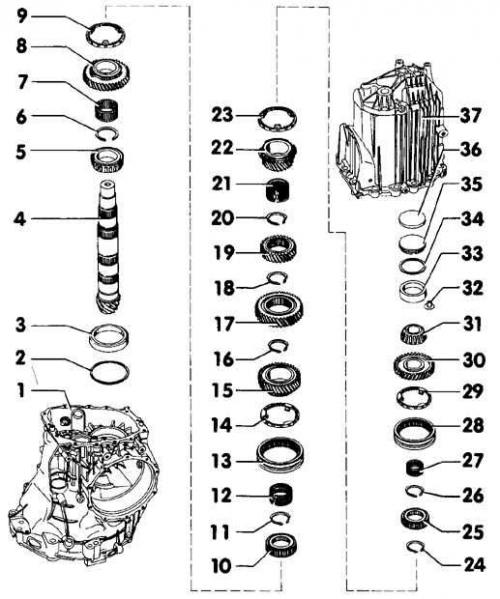
- 1. Main gear housing
- 2. Washer S3
- 3. Double row tapered roller bearing - inner race
- 4. Drive gear
- 5. Double row tapered roller bearing - inner race
- 6. Retaining ring
- 7. Needle bearing - 1st gear
- 8. First gear pinion
- 9. Synchronizer ring - 1st gear
- 10. Synchronizer hub - 1st/2nd gear
- 11. Retaining ring
- 12. Needle bearing - 2nd gear
- 13. Sliding clutch - 1st / 2nd gear
- 14. Synchronizer ring - 2nd gear
- 15. 2nd gear pinion
- 16. Retaining ring
- 17. 3rd gear pinion
- 18. Retaining ring
- 19. 4th gear pinion
- 20. Retaining ring
- 21. Needle bearing - 5th gear
- 22. 5th gear pinion
- 23. Synchronizer ring - 5th gear
- 24. Retaining ring
- 25. Synchronizer hub - 5th gear/reverse gear
- 26. Retaining ring
- 27. Needle bearing - reverse gear
- 28. Sliding clutch - 5th gear/reverse gear
- 29. Synchronizer ring - reverse gear
- 30. Reverse gear
- 31. Tapered roller bearing - inner race
- 32. Locking threaded sleeve for outer race of tapered roller bearing
- 33. Tapered roller bearing - outer race
- 34. Washer S4
- 35. Pressure plate
- 36. Washer
- 37. Gearbox housing
Warning: Pinion 4 corresponds to the ring gear (pair ring gear/pinion gear). When replacing the ring gear/pinion gear pair, adjust the installation of the pinion gear as well as the hollow shaft and ring gear.
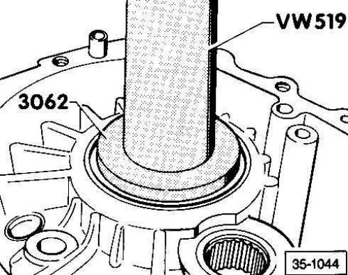
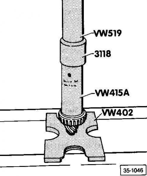
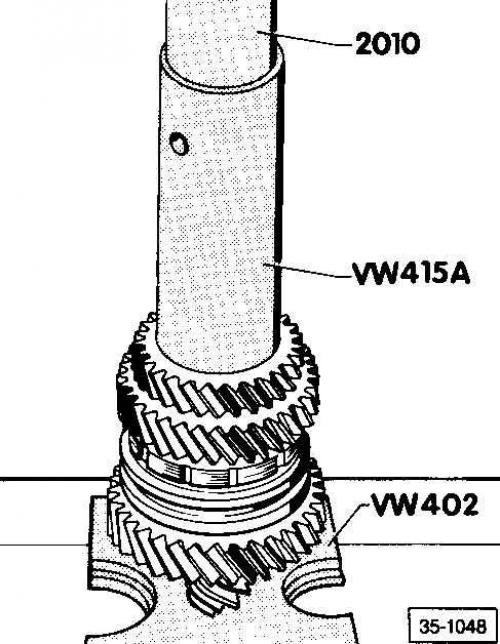
Warning: The protruding edge of synchronizer hub 10 faces 2nd gear. Remove hub 10 together with 1st gear pinion. Use thrust plates VW 401 and VW 402. Install using mandrel VW 415A and sleeve VW 519.
Warning: The groove of gear 17 faces the 4th gear gear.
Warning: The edge of gear 19 faces the 3rd gear gear.
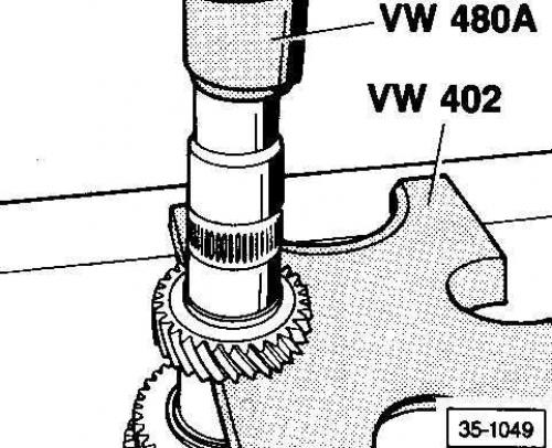
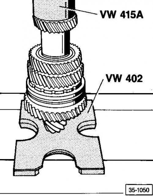
Warning: The protruding edge of hub 25 faces the 5th gear pinion. Remove hub 25 together with the 5th gear pinion. Install using sleeve 2010.
Warning: It is not necessary to install the 32 threaded locking sleeve when replacing the outer race (this bushing is only needed for production).
Warning: Washer 36 compensates for expansion depending on temperature (heating). To remove, drill a hole in the washer and remove it with a screw.
Installing the synchronizer spring into the gear
Install the spring (indicated by the arrow) into the gear, placing the pointed end into the groove.
Checking the synchronizer ring for wear
1. Press the synchronizer ring against the sliding sleeve and measure the clearance a using a feeler gauge at points A, B and C.
2. Add the resulting values and divide the sum by 3.
3. The obtained value should not be less than 0.5 mm.
Installing the 1st/2nd gear sliding clutch
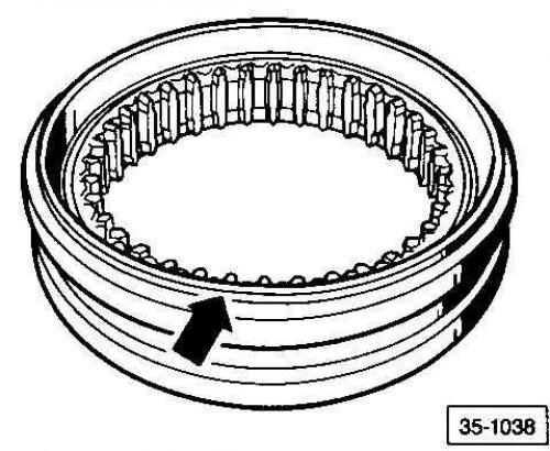
The side with the groove should face the 1st gear.
Removal the 3rd gear
- A = puller 22–115 mm, type Kukko 17/2
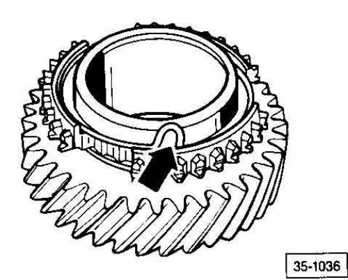
Installing 3rd gear pinion
Installation position: The groove should face the 4th gear.
Removal the 4th gear
Installing the 4th gear
Removal the synchronizer hub
Remove the synchronizer hub together with the 5th gear pinion. Use puller A for 22–115 mm, such as Kukko 17/2.
Synchronizer Ring Identification
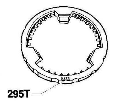
The production of rings with more than 3 tongues has been discontinued.
Removal the inner race of a tapered roller bearing
Remove the inner race together with the reverse gear pinion. Use puller A for 22-115 mm, such as Kukko 17/2.
Installing the inner race of a tapered roller bearing
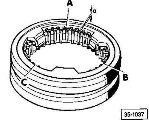
Installing the 5th/Reverse Sliding Clutch
Diagonal strip 1 faces the reverse gear pinion.
The side with groove 2 faces the 5th gear gear.
Removal the locking threaded sleeve
Use a 22-115mm puller A, such as Kukko 17/2. No bushing is required when replacing the outer race (this bushing is only needed for production).
Removal the outer race of a tapered roller bearing
1. Screw the special bolt for removal into the release plate (m10 bolt, 50 mm long, ground down at one end to diameter M8).
2. Remove the release plate and outer race from the crankcase using a hammer
Installing the outer race of a tapered roller bearing
Installing a Tapered Roller Bearing Snap Ring
Find the thickest circlip that will fit and install it. The required thickness of the synchronizer hub circlips and the thickness of the 3rd/4th gear circlips are determined in the same way as the tapered roller bearing circlip thickness.
List of retaining rings
| Thickness of retaining ring, mm | Number |
| Retaining ring 1 | |
|
2.00
|
902 945.01
|
|
2.02
|
902 950.02
|
|
2.04
|
902 950.03
|
|
2.06
|
902 950.04
|
|
2.08
|
902 950.05
|
|
2.10
|
902 950.06
|
| Retaining ring 2 (blue) | |
|
1.90
|
902 947.01
|
|
1.93
|
902 947.02
|
|
1.96
|
902 947.03
|
|
1.99
|
902 947.04
|
|
2.02
|
902 947.05
|
| Retaining ring 3 (blue) | |
|
2.50
|
902 947.06
|
|
Retaining ring 4
| |
|
1.90
|
902 946.02
|
|
1.93
|
902 946.03
|
|
1.96
|
902 946.04
|
|
1.99
|
902 946.05
|
|
2.02
|
902 946.06
|
| Retaining ring 5 | |
|
1.87
|
902 952.01
|
|
1.90
|
902 952.02
|
|
1.93
|
902 952.03
|
|
1.96
|
902 952.04
|
| Retaining ring 6 (brown) | |
|
2.00
|
902 945.01
|
| Retaining ring 7 (blue) | |
|
1.90
|
902 944.01
|
|
1.93
|
902 944.02
|
|
1.96
|
902 944.03
|
|
1.99
|
902 944.04
|
|
2.02
|
902 944.05
|
|
2.05
|
902 944.06
|
Installation location/selection of retaining rings
The retaining rings are numbered according to their position on the drive shaft.
Retaining rings 1, 2, 4, 5 and 7 must be selected.
The thickness of retaining rings 3 and 6 is always constant.
Differential assembly
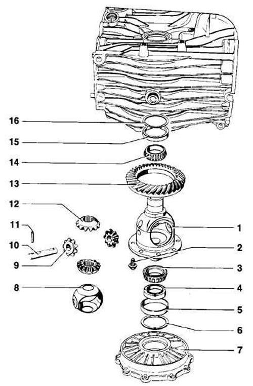
- 1. Differential housing
- 2. Ring gear bolt
- 3. Large roller bearing - inner race
- 4. Speedometer drive gear
- 5. Large roller bearing - outer race
- 6. Washer S1
- 7. Lid
- 8. Thrust washer
- 9. Satellites
- 10. Axle of satellites
- 11. Satellite axis pin
- 12. Half-axle gears
- 13. Toothed crown
- 14. Small roller bearing - inner race
- 15. Small roller bearing - outer race
- 16. Washer S2
Warnings
- When replacing differential housing 1, adjust the ring gear installation.
- Use bolts 2 of the required specification only. Tighten them evenly in a diagonal pattern.
- Install large roller bearing 3 using tools VW 295 and VW 551.
- Mark the thickness of washer 6.
- Before installing thrust washer 8, lubricate it with transmission oil.
- Remove the satellite axle 10 using a punch after removing the satellite axle pin.
- Remove the satellite axis pin 11 using a punch.
- Toothed ring 13 and pinion are matched to each other. When replacing the toothed ring/pinion pair, make adjustments. To install, heat to 100°C and install using centering pins.
- Install small roller bearing 14 using sleeve 40–21.
- Mark the thickness of washer S2.