



Table of contents: Fuel tank, front-wheel drive vehicle ↓ Removal and installation of fuel.… ↓ Removal and installation fuel… ↓ Fuel delivery module and fuel level… ↓ Removal and installation the fuel… ↓ Removal and installation the fuel… ↓
Fuel tank, front-wheel drive vehicle
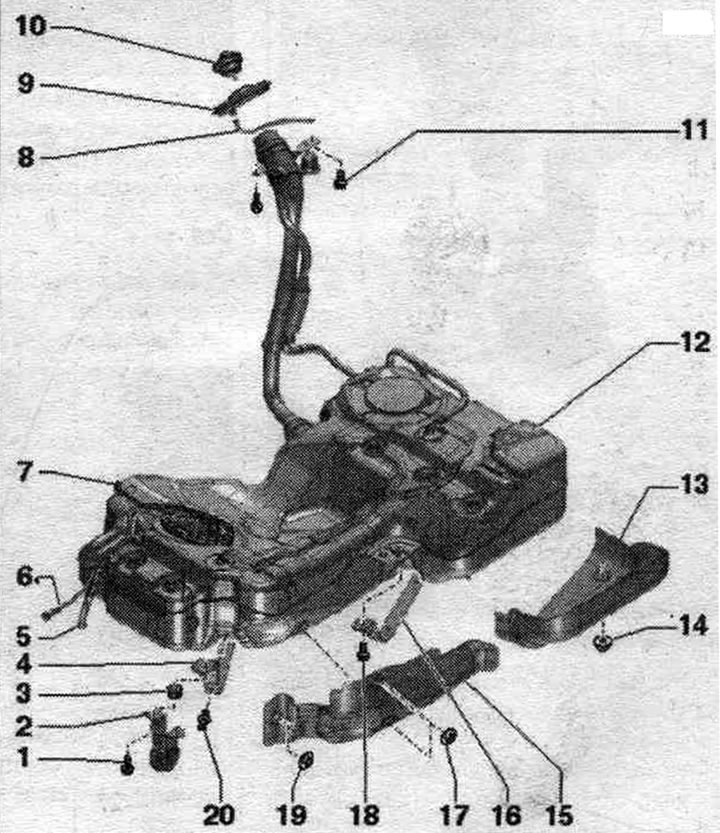
1. Bolt.
2. Muffler suspension.
3. Buffer.
4. Tie-down clamp: various lengths.
5. Fuel supply. highway: to additional fuel. pump "V393"; don't overdo it; clipped to fuel. tank.
6. Reverse fuel. line: from the fuel cooler; don't overdo it; clipped to fuel. tank; to disconnect, press the fitting lock.
7. Fuel line: only on vehicles with independent heater: to the independent heater metering pump; don't overdo it; clipped to fuel. tank; to disconnect, press the fitting lock.
8. Overflow hose: hung on the bumper bracket.
9. Rubber bowl.
10. Lid: screw on until it clicks into place; attached to the fuel filler flap assembly. tank using a clamp.
11. Bolt: for fastening the fuel filler neck. tank; to remove electrostatic discharge; 20 Nm.
12. Fuel tank.
13. Heat shield fuel. tank.
14. Nut: 2 Nm.
15. Heat shield fuel. tank.
16. Tie-down clamp: note the difference in length.
17. Nut: 2 Nm.
18. Bolt: 20 Nm.
19. Nut: 2 Nm.
20. Lock clip.
Flange cover - tightening torque
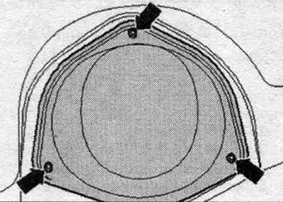
Tighten the arrow bolts to 1.5 Nm.
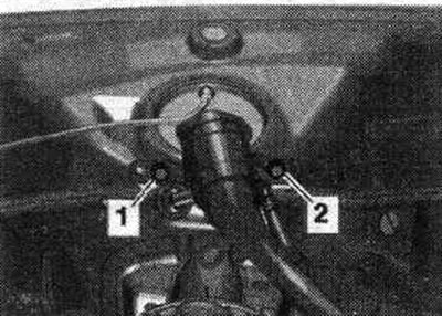
Fuel filler neck ground contact
Make sure that there is fluid on the threaded connections "1" and "2" of the fuel filler neck. there is no corrosion on the tank, as this could affect the quality of contact with the body ground. Danger from electrostatic charge. After installation, check the electrical connection using an ohmmeter. contact of the washer on the filler neck with any unpainted area on the body. Set value: approx. 0 Ohm.
Fastening details of the tensioning strap
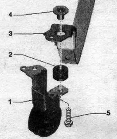
1. Suspension system. exhaust, front left. 2. Buffer. 3. Tightening clamp. 4. Expansion sleeve. 5. Bolt.
Removal and installation of fuel. tank with attachments
Pumping fuel out of the tank. Remove the rear seat. Unscrew the "arrow" flange cover. Disconnect plug "1" from the flange.
Cars with independent heater: Disconnect plug connector "2" of the independent heater metering pump from the flange.
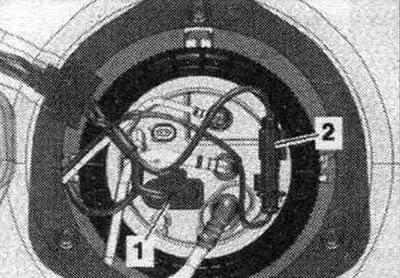
All
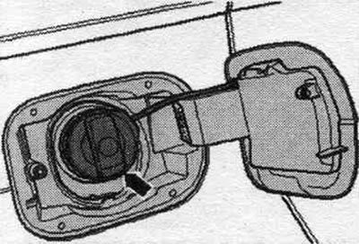
Open the fuel hatch. tank. Clean the area around the fuel filler neck. tank. Remove the "arrow" cap from the fuel filler neck. tank.
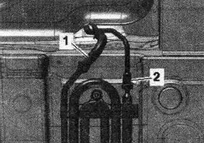
Remove the right rear wheel. Remove the rear right fender liner. Loosen bolts "1" and "2" of the oil supply line. Remove the rear part of the system. exhaust. Remove the rear axle. Disconnect the return fuel line. highway "2" by pressing the release button. Disconnect the fuel supply line. highway "1".
Cars with independent heating: Additionally, disconnect the fuel from the metering pump. the main line going to the independent heater. Disconnect the plug connector from the metering pump.
All
To maintain balance, place the engine and gearbox bracket under the fuel tank. Support the fuel tank. tank with engine and gearbox lift.
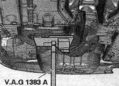
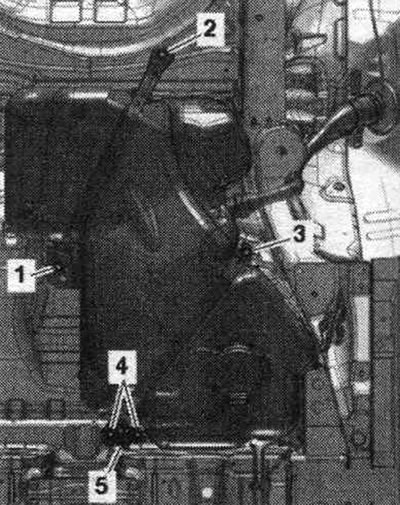
Unscrew bolts "1...5" and remove bracket "6" of the exhaust system. Lower the fuel tank. tank using an engine and gearbox lift, holding the fuel. tank with hand.
Installation
Installation in reverse order. Secure all hose connections with hose clamps of the appropriate series. Make sure the fuel lines are secured to the fuel tank. tank. Place fuel. tank using tension straps and an engine and gearbox lift on the bottom of the car. When installing the fuel. tank, pay attention to the correct entry of the filler neck into the body opening. Install bracket "5" of the exhaust system and tighten bolts "1...4" of the clamping bands. Make sure that there is fluid on the threaded connections "1" and "2" of the fuel filler neck. there is no corrosion on the tank, as this could affect the quality of contact with the body ground. Tighten bolts "1" and "2" of the fuel filler neck. tank. Install the rear axle. Install the rear part of the system. exhaust. Install the rear right fender liner. Install the flange cover. Install the rear seat.
Cars with independent heater: Bleeding the fuel supply. highways.
Removal and installation fuel overflow protection when refueling
Open the fuel hatch. tank. Clean the area around the fuel filler neck. tank. Unscrew the "arrow" cap of the fuel filler neck. tank.
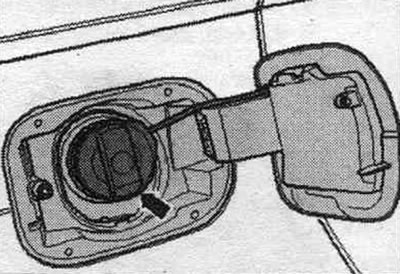
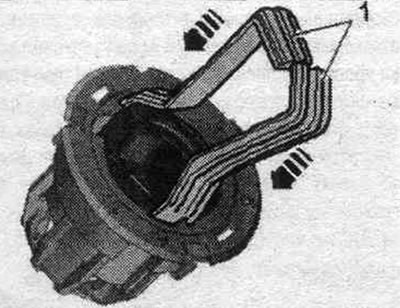
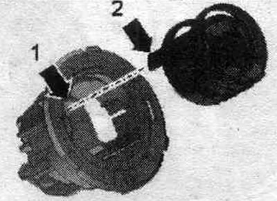
Insert the release strips "1" into both guides in the fuel filler nipple until they stop. "arrow" tank, as shown in the figure. The recesses of the release strips face each other. The release strips click into place. When the unlocking strips are inserted, the fuel overflow protection "1" is unlocked and can be removed.
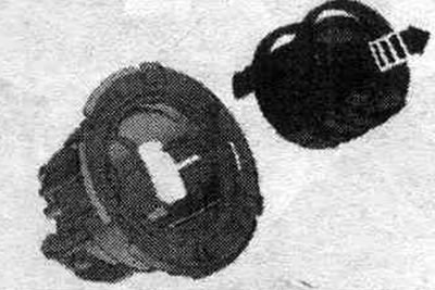
Remove the fuel overflow protection from the fuel filler neck of the "arrow" tank when refueling.
Installation
Install protection against fuel overflow when refueling into the fuel filler neck. tank. The locking lug "arrow 2" must engage with the guide "arrow 1" on the fuel spill protection during refueling. Installation from the driving side is not possible. Press the fuel overflow protection into the fuel filler neck until it clicks into place. tank.
Danger from electrostatic charge. The fuel tank is connected to ground via a fuel overflow protection device when refueling. If the fuel overflow protection is out of order, then simply installing it is not enough. As a replacement, it is necessary to install an exchange part without protection against overflow of fuel during refueling.
Fuel delivery module and fuel level sensor
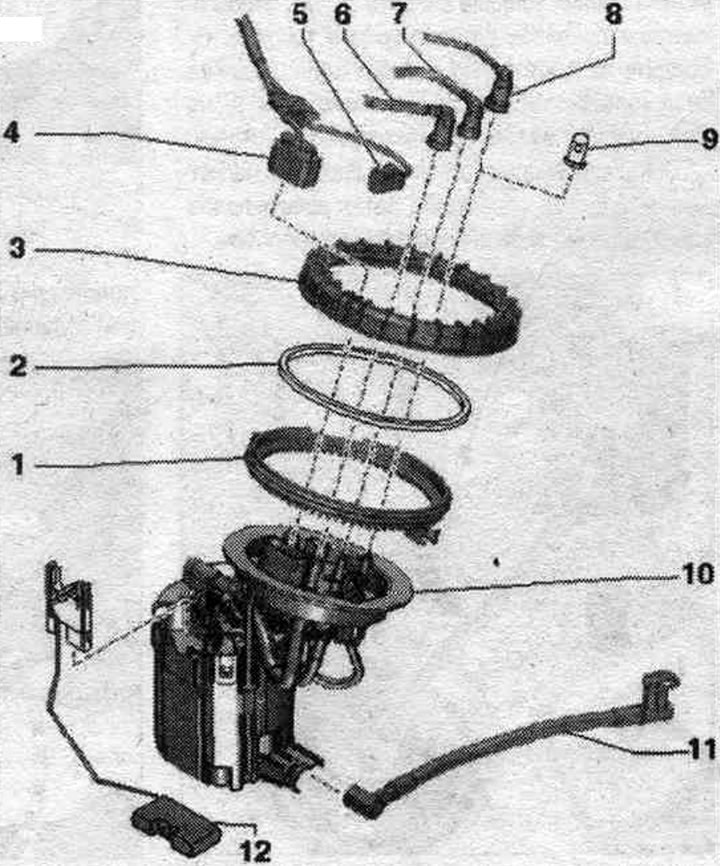
1. Threaded ring.
2. Seal cuff: replace; install dry.
3. Union nut: replace; 120 Nm; removal and installation using the T40068A socket wrench.
4. Electrical connector: for fuel injection. pump "G6" and fuel level sensor "G".
5. Electrical connector: only for vehicles with independent heater: to the independent heater metering pump.
6. Fuel supply. highway: to additional fuel. pump; don't overdo it; to disconnect from the flange, press the fitting lock; when installing, observe the direction (feed or return), indicated by the arrow on the shut-off flange; clipped to fuel. tank.
7. Reverse fuel. line: from the fuel cooler; don't overdo it; to disconnect from the flange, press the fitting lock; when installing, observe the direction (feed or return), indicated by the arrow on the shut-off flange; clipped to fuel. tank.
8. Fuel line; only for vehicles with independent heating: to the independent heating metering pump; don't overdo it; to disconnect from the flange, press the fitting lock; clipped to fuel. tank.
9. Cap: for vehicles without independent heating.
10. Fuel supply unit: check the supply of booster fuel. pump "G6"; after installation, fill the car with at least 5 liters of fuel.
11. Suction pipeline.
12. Fuel level sensor "G".
Electrical test of the fuel pre-supply pump "G6"
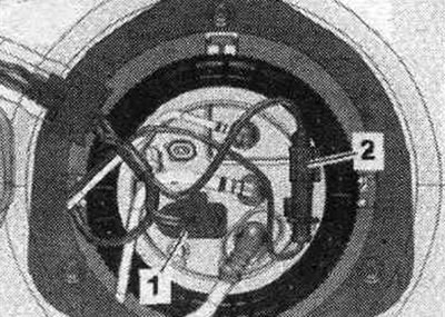
Remove the rear seat. Unscrew the "arrow" flange cover. Disconnect plug "1" from the flange. "Pos. 2" should not be taken into account.
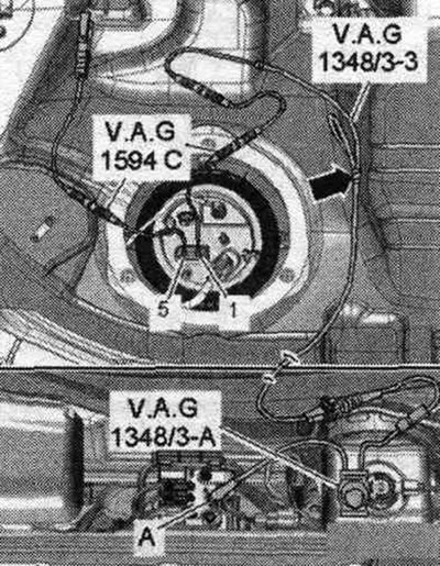
Connect the remote control device for VAG 1348 "VAG 1348/3A" with adapter cable "VAG 1348/3-3" using an auxiliary wire from the auxiliary kit. and measuring instruments "VAG15940" to contact "1". 2nd contact of the adapter cable plug "VAG 1348/3-3" cover the "arrow" with electrical tape to prevent short-circuiting. Connect contact "5" to the body ground using the wire from the "VAG 1594C" measuring kit. Move the remote control button for the VAG 1348 "VAG 1348/3A" forward to the motorcycle. compartment.
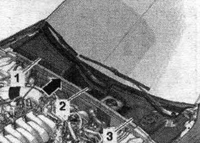
Remove the "arrow" gasket. Unfasten and remove the radiator tank cover assembly (depending on the design option) or separate part "2". "Pos. 1, 3" should not be taken into account.
Unlock the lock "arrow A" and open the cover "arrow B".
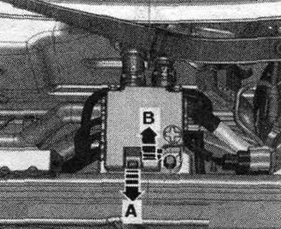
Connect the clamp terminal to the terminal of the external starter current source "U6" "pos. A" in the terminal block for the key. 30 "TV22" in a water drainage box. Press the remote control switch. You should be able to hear the fuel pump running. pump "G6". Since the fuel. the pump operates silently, necessary during fuel check. pump to avoid surrounding noise. If the sound of the pump running is not heard, remove the fuel delivery module. Check the correct connection and continuity of the wires between the flange and the fuel pump. If no damage to the wires is found, replace the fuel delivery module. Install the fuel delivery module.
Removal and installation the fuel supply unit
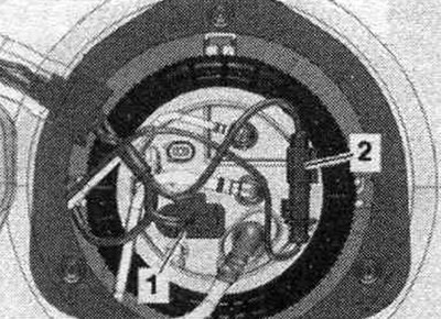
If necessary, pump out fuel from the fuel tank. tank. If necessary, move the front passenger seat as far forward as possible. Remove the rear seat. Unscrew the "arrow" flange cover. Disconnect plug "1" from the flange.
Cars with independent heater: Disconnect plug connector "2" of the independent heater metering pump from the flange and set it aside.
All
Disconnect the fuel. lines "2" and "3" from the flange by pressing the release buttons.
Cars with independent heater: Disconnect the fuel line. line "1" from the independent heater metering pump by pressing the release button.
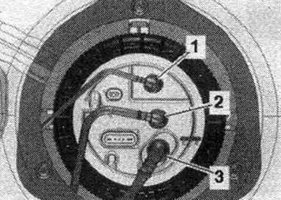
All
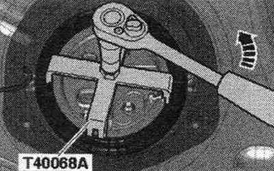
Loosen the union nut with the T40068 A "arrow" union nut wrench. When loosening the union nut, the plastic clip on the threaded ring will break off. Ignore this.
Remove flange "2" from the fuel tank and remove the seal. cuff "1".
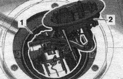
Tilt the fuel supply module "1" towards the left side of the vehicle "arrow" and do not completely remove it from the fuel tank. tank. When removing the fuel delivery module, make sure that the float of the fuel level sensor "G" does not bend. Remove the fuel level sensor "G" "pos. 2" from the fuel hole. tank and remove the fuel supply module with the suction line from the fuel. tank.
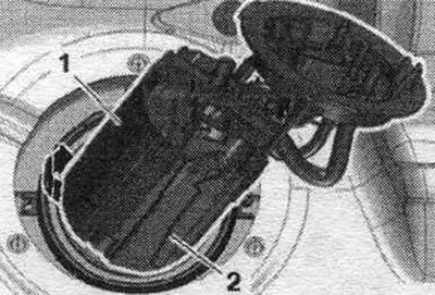
Installation
Installation in reverse order. Replace the seal. cuff and union nut. When installing the fuel delivery module, make sure that the fuel level sensor float "G" is not bent. Ensure that the fuel is seated tightly. hoses. Bend down the suction line "3", located on the fuel supply module "2" "arrow A". First, insert the suction line into the fuel. tank "arrow B". Then insert float "1" of fuel level sensor "G" into the fuel tank.
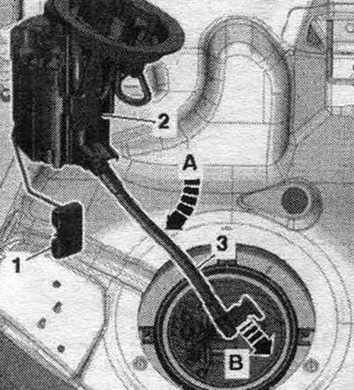
Tilt the fuel delivery module "1" to the left side of the vehicle and insert it into the fuel tank. tank "arrow", while monitoring the correct position of the fuel level sensor "2". Install a new seal. cuff "1" over flange "2" and insert into the groove on the fuel. tank. Insert your left hand into the union nut "1" and, with the same hand, forcefully install flange "2" into the "arrow" mounting position. Cover plate "4" on the blind flange should be located between tongues "3" and "5" on the threaded ring.
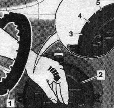
Insert the union nut "1" into the left hand, holding the nut with the right hand, and press firmly on the flange "2" with the left hand "arrow". With the right hand, place the union nut "1" in such a way that the double rib "5" of the ribbing is above the flange overlay "3" (approx. "in the 10 o'clock position"). Then the union nut will enter the threaded nipple "4" more easily.
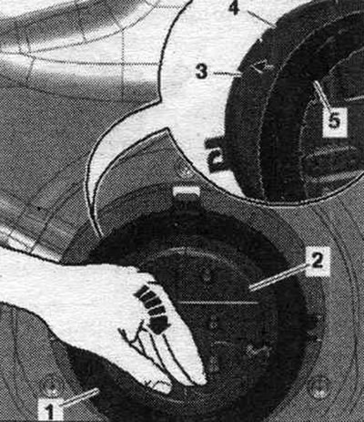
Press firmly on the flange downwards "arrow". With the right hand, turn the union nut 480° so that the double rib "1" is in the "2 o'clock position", while pressing firmly on the flange downwards with the left hand.
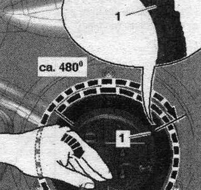
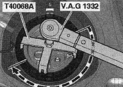
When tightening the union nut, apply firm pressure to the flange to prevent it from turning. Tighten the flange union nut with the T40068 A union nut wrench.
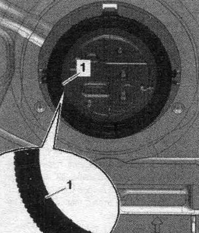
Check: Double jumper "1" should be in the "position between 7 and 8 o'clock".
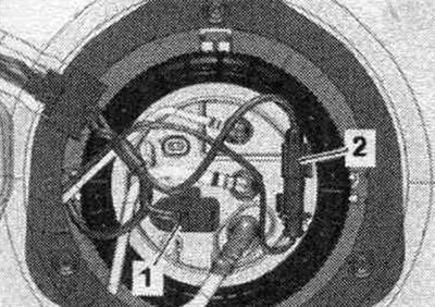
Connect fuel. highways "1,2,3". Connect the plug connectors. Install the flange cover. Install the rear seat. After installing the fuel supply unit, fill the car with at least 5 liters of fuel.
Cars with independent heater: Bleeding the fuel supply. highways.
Checking the fuel level sensor "G"
Remove the rear seat. Unscrew the "arrow" flange cover. Disconnect plug "1" from the flange. "Pos. 2" should not be taken into account.
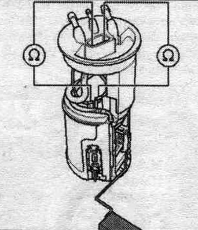
Connect a multimeter to check the resistance between contacts "2" and "4." Fuel level sensor "G" is installed: sensor on the lower stop: approx. 280 Ohms; upper stop sensor: approx. 65 Ohm.
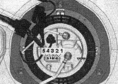
If the measured value is 0 ohms, then there is a short circuit; if it is equal to infinity ohms, there is an open circuit. To check the "Tank Full" or "Tank Empty" resistance values, you must remove the fuel delivery module. With the fuel level sensor removed, the following values are obtained as a result of the greater float deviation.
Fuel level sensor "G" removed: sensor on the lower stop: approx. 288 Ohm; sensor at the upper stop: approx. 57 Ohm. Connect a multimeter to check the resistance between contacts "3" and "4". Fuel level sensor "G" installed or removed: in any position of the sensor: approx. 340 Ohm.
Installation in reverse order. Install the flange cover. Install the rear seat.
Removal and installation the fuel level sensor "G"
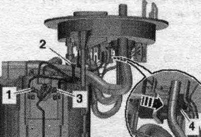
When reassembling, install the cable tie in the place where it was originally installed. Removing the fuel supply unit. Disconnect connector "4" by pressing the "arrow" latch. Cut cable tie "2" and release the plug connector. Unlock clamps "1" and "3" and remove fuel level sensor "G" upwards.
Installation
Installation in reverse order. Insert the fuel level sensor "G" into the fuel delivery module guides and press down until it clicks into place. Connect the plug connector and make sure it is securely fastened. Install the fuel delivery module.
[The original article is posted on the resource AUDImanual.ru]