Table of contents: Multifunctional steering wheel ↓ Up to model year 2012 ↓ 4-spoke steering wheel installation… ↓ 3-spoke steering wheel installation… ↓ Removal and installation… ↓ Removal and installation… ↓ Removal and installation… ↓ Removal and installation the… ↓ Removal and installation the… ↓
Multifunctional steering wheel
To achieve the best control over the infotainment system, telephone and navigation system, a series of buttons are built into the steering wheel. With Tiptronic add. control switches are installed on the left and right. this system. Used multifunctional steering wheel "J453" (under the right button) reads information from the keys and transfers it to the LIN data bus to the control unit. steering electronics. j527 speakers. From used steering wheel electronics. the information is transmitted via the CAN bus (Comfort) and the diagnostic interface of the data bus "J533" to individual devices from the "J527" column. Troubleshooting. carried out in the Guided Troubleshooting mode.
Up to model year 2012
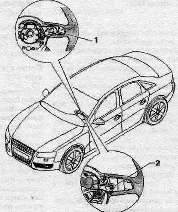
1. Multifunctional buttons.
2. Bolt: 3 Nm.
4-spoke steering wheel installation diagram (since 2013 model year)
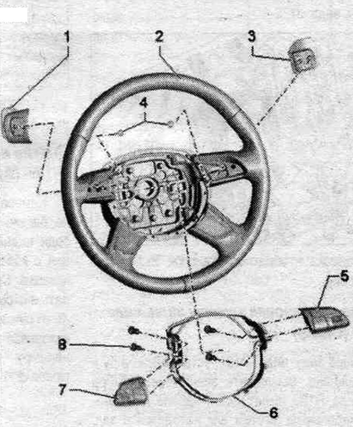
1. Tiptronic switch in the steering wheel below "E439".
2. Steering wheel with 4 spokes.
3. Tiptronic switch in the steering wheel above "E438".
4. Bolt: 1.2 Nm.
5. Multifunctional buttons on the steering wheel on the right "E441".
6. Decorative canopy.
7. Multifunctional buttons on the steering wheel on the left "E440".
8. Bolt: 1.2 Nm.
3-spoke steering wheel installation diagram (since 2013 model year)
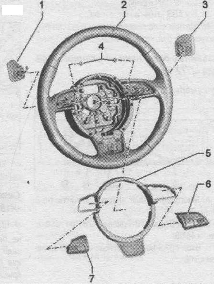
1. Tiptronic switch in the steering wheel below "E439".
2. 3-spoke steering wheel.
3. Tiptronic switch in the steering wheel above "E438".
4. Bolt: 1.2 Nm.
5. Decorative canopy.
6. Multifunctional buttons on the steering wheel on the right "E441".
7. Multifunctional buttons on the steering wheel on the left "E440".
Removal and installation multifunction buttons (up to model year 2012)
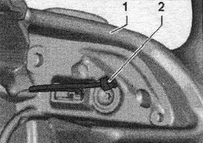
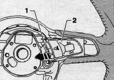
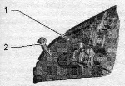
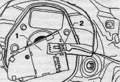
Turn off the ignition. Remove the driver's airbag. Remove the decorative ring from the steering wheel. Unlock and disconnect connector "1" from button "2". Press button "2" away from the steering wheel in the direction of the arrow. Turn the multifunction button.
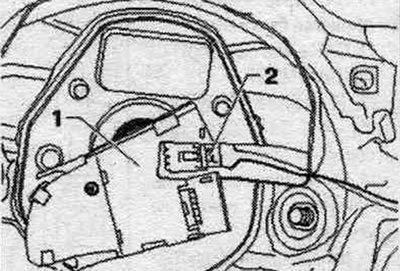
Unlock and disconnect the plug connector "2" to the Tiptronic switch on the multifunction steering wheel button "1" and remove the button.
Installation in reverse order.
Removal and installation multifunction buttons on a 4-spoke steering wheel (since 2013 model year)
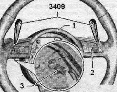
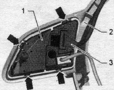
Multifunction buttons "2" are bolted to decorative cover "1." Decorative cover "1" is secured to the steering wheel together with multifunction buttons "2." Each multifunction button "2" has a separate locking clip "3." When removing, be careful to first manually detach decorative cover "1" (approx. 5 mm), then use wedge "3409" to release locking clips "3" from multifunction buttons "2," and then remove decorative cover "1" and multifunction buttons "2.".
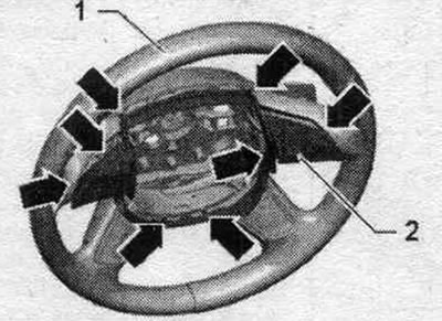
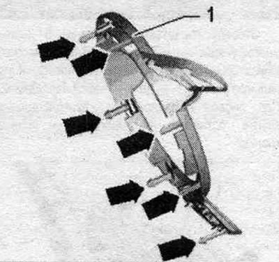
Decorative trim fasteners
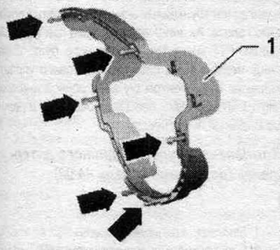
1. Decorative canopy.
"Arrows" clamps.
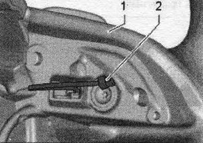
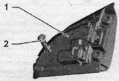
Multifunctional button latches
1. Multifunctional button.
2. Retainer.
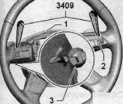
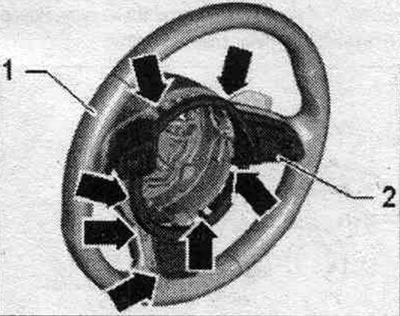
Turn off the ignition. Remove the driver's airbag. Remove the connecting lines from the guides in the steering wheel. Manually gently detach the decorative cover "2" with the multi-function "arrow" buttons and detach them approx. 5 mm from the steering wheel "1".
Unlock multifunction buttons "2" using wedge "3409" next to locking pins "3." Install wedge "3409" as shown. Pay attention to the connectors to Tiptronic switches "2." Disconnect this connector "2" from the multifunction buttons. Remove the decorative trim along with the multifunction buttons from the steering wheel. The multifunctional buttons are bolted to the decorative cover. Disconnect the multifunction button connector.
Loosen bolts "3" and push multifunction button "2" out of decorative cover "1". The auxiliary wire to the right multifunction button remains on the multifunction button.
Installation
Installation in reverse order. Install the decorative trim with multifunctional buttons on the steering wheel. Take into account that the connecting cable is switched. Tiptronic "2" was routed as shown in the picture. Route the remaining connecting cable, including the connector, through the guides in the steering wheel. Press the decorative cover "2" together with the multifunctional buttons into the steering wheel "1" until it is securely fixed. Finally, check again that the wires in the steering wheel are routed correctly.
Removal and installation multifunction buttons on a 3-spoke steering wheel (since 2013 model year)
Multifunction buttons "2" are riveted to decorative cover "1." Decorative cover "1" is secured to multifunction buttons "2" on the steering wheel. Each multifunction button "2" has a separate locking clip "3." When removing, be careful to first manually detach decorative cover "1" (approx. 5 mm), then use wedge "3409" to release locking clips "3" from multifunction buttons "2," and then remove decorative cover "1" and multifunction buttons "2.".
Decorative trim fasteners
1. Decorative canopy.
"Arrows" clamps.
Multifunctional button latches
1. Multifunctional button.
2. Retainer.
Turn off the ignition. Remove the driver's airbag. Remove the connecting lines from the guides in the steering wheel. Manually gently detach the decorative cover "2" with the multi-function "arrow" buttons and detach them approx. 5 mm from the steering wheel "1".
Unlock multifunction buttons "2" using wedge "3409" next to locking pins "3." Install wedge "3409" as shown. Pay attention to the connectors to Tiptronic switches "2." Disconnect this connector "2" from the multifunction buttons. Remove the decorative trim along with the multifunction buttons from the steering wheel. Multifunctional buttons are connected with clips to a decorative cover.

Disconnect the connector "3" from the multifunction steering wheel button "1". Release the "arrow" latches and push the multifunction button "1" out of the decorative cover "2". The auxiliary wire to the right multifunction button remains on the multifunction button.

Installation
Installation in reverse order. Install the decorative trim with multifunctional buttons on the steering wheel. Take into account that the connecting cable is switched. Tiptronic "2" was routed as shown in the picture. Route the remaining connecting cable, including the connector, through the guides in the steering wheel. Press the decorative cover "2" together with the multifunctional buttons into the steering wheel "1" until it is securely fixed. Finally, check again that the wires in the steering wheel are routed correctly.
Removal and installation the Tiptronic switch (up to model year 2012)
Turn off the ignition. Remove the driver's airbag. Remove the decorative ring from the steering wheel. Press button "2" in the direction of the arrow from the steering wheel. Turn the multifunction button.
Unlock and disconnect plug connector "2" from multifunction button "1".
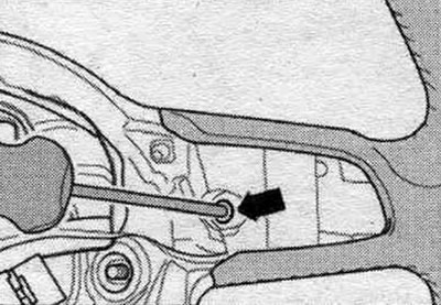
Unscrew the "arrow" screw and remove the Tiptronic switch back.
Installation in reverse order.
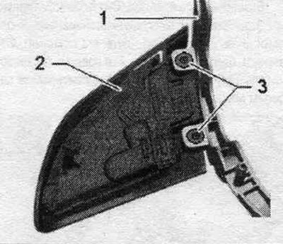
Removal and installation the Tiptronic switch (since 2013 model year)
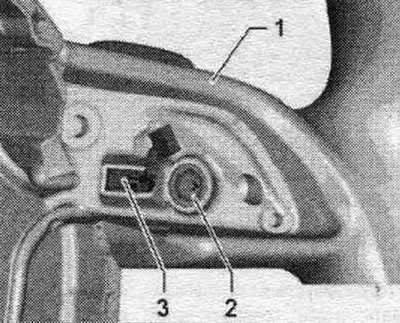
Turn off the ignition. Remove the decorative cover along with the multi-function buttons (4-spoke steering wheel), (3-spoke steering wheel). Unscrew the bolts "2" on the steering wheel "1" and remove the Tiptronic switch "3" together with the connecting cable in a backward motion.
Installation
Installation in reverse order. Pay attention to the position of the connecting cable "2" to the multi-function button.