
Antenna system, Sedan
The antenna system consists of rear antennas. glass and antennas on the roof. In the antenna of the radio, telephone, and navigation system "R52" (antenna on the roof) installed: navigation antenna. syst. "R50", Telephone Antenna "R65", Additional Antenna. heater "R182", satellite antenna "R170" (for the US only).
System with phase shifter (cAN/MMI radio with calendar, weeks 45/08): Antenna amplifier 3 "R112" (AM/FM1/FM2/FZV) on the D pillar on the left (CAN), Antenna amplifier 3 "R112" (AWFM1/FM2HV1WZV) on the D-pillar on the left (MMI), Antenna amplifier 2 "R111" (DAB) on the D-pillar on the right (CAN), Antenna amplifier 2 "R111" (DAB/TV3) on the D-pillar on the right (MMI), Antenna radio, telephone, navigation system "R52" (GPS/GSM/RC/SAT), antenna on the roof.
Switching phase shifter system (MMI until calendar week 44/08): Antenna amplifier 3 "R112" (HF/ZF/TV1/TV2/FZV) on the D-pillar (left), Antenna amplifier 2 "R111" (FM3/DAB/VICS/TV3) on the D-pillar (on the right), antenna for radio, telephone, navigation system "R52" (GPS/GSM/RC/SAT), antenna on the roof.
The "R52" antenna for radio, telephone, and navigation systems with SAT connection is only valid for the USA. The "R111" antenna amplifier 2 with DAB connection is only valid for Europe.
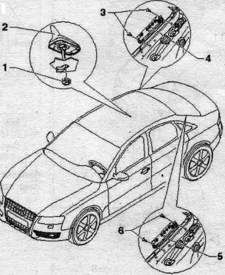
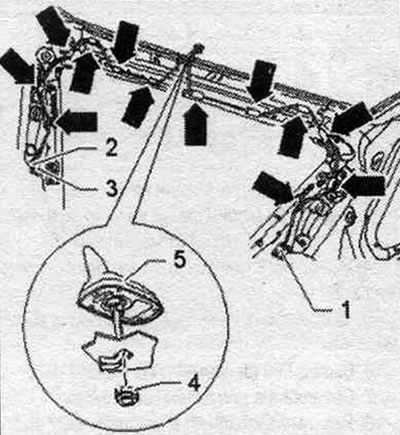
1. Nut: 6 Nm.
2. Antenna for radio, telephone, navigation. syst. "R52".
3/6. Bolt: 2 Nm.
4. Antenna amplifier 2 "R111".
5. Antenna amplifier 3 "R112".
Connectors
Antenna amplifier 3 "R112" (cAN radio)
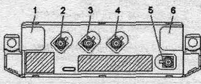
1. Connection for antennas on glass.
2. Not busy.
3. Connector (yellow) AM/FM1 to the "R" radio.
4. FM2 connector (white) to the "R" radio.
5. FZV connector (gray) to the central control unit. syst. comfort "J393".
6. Connection for antennas on glass.
Antenna amplifier 3 "R112" (MMI until calendar week 44/08)
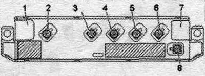
1. Connection for antennas on glass.
2. TV1 output (brown) to TV tuner "R78".
3. ZF output (yellow) from the "R" radio.
4. Output FM3 (purple) from antenna amplifier 2 "R111".
5. High frequency output (white) to radio "R".
6. TV2 output (green) to TV tuner "R78".
7. Connection for antennas on glass.
8. FZV connector (gray) to the central control unit. syst. comfort "J393".
Antenna amplifier 3 "R112" (MMI with calendar weeks 45/08)

1. Connection for antennas on glass.
2. TV1 output (brown) to TV tuner "R78".
3. Connector (yellow) AM/FM1 to the "R" radio.
4. Not busy.
5. FM2 connector (white) to the "R" radio.
6. TV2 output (green) to TV tuner "R78".
7. Connection for antennas on glass.
8. FZV connector (gray) to the central control unit. syst. comfort "J393".
Antenna amplifier 2 "R111" (until calendar week 44/08)

1. Connection for antennas on glass.
2. DAB output (black) to the "R" digital radio "R147" (Europe).
3. Output FM3 (purple) from antenna amplifier 3 "R112" (MMI).
4. TV3 connector (green) to TV tuner "R78" (MMI).
Antenna amplifier 2 "R111" (from calendar week 45/08)
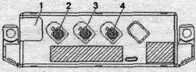
1. Connection for antennas on glass.
2. DAB connector (black) to the "R" radio.
3. Not busy.
4. TV3 output (green) to TV tuner "R78".
Removal and installation the roof antenna
Roof antenna, radio, telephone, and navigation system antenna "R52" (GSM/GPS/RC/SAT), has max. 4 connections. The antenna wires are located on the left and right D-pillars. To remove the antenna for the radio, telephone, and navigation system "R52", it is necessary to remove the D-pillar trim and lower the ceiling panel. Turn off the ignition. Remove the D-pillar trim on the left and right. Remove the ceiling panel completely and place it on the front panel. Unlock and disconnect plug connectors "1", "2" and "3" from the antenna wires. Disconnect the antenna wires of the radio, telephone, and navigation system antenna "R52" "arrows". Unscrew the nut "4". Remove the antenna of the radio, telephone, and navigation system "R52" "5" from the roof upwards.
Installation
Route the antenna wires through the hole in the roof and carefully install the antenna for the radio, telephone, and navigation system "R52". Ensure the seal is correctly positioned. Installation in reverse order.