
Table of contents: Antenna system, Avant ↓ Connectors ↓ Removal and installation the antenna… ↓ Removal and installation antenna… ↓ Removal and installation of the… ↓ Removal and installation antenna… ↓ Removal and installation the roof… ↓
Antenna system, Avant
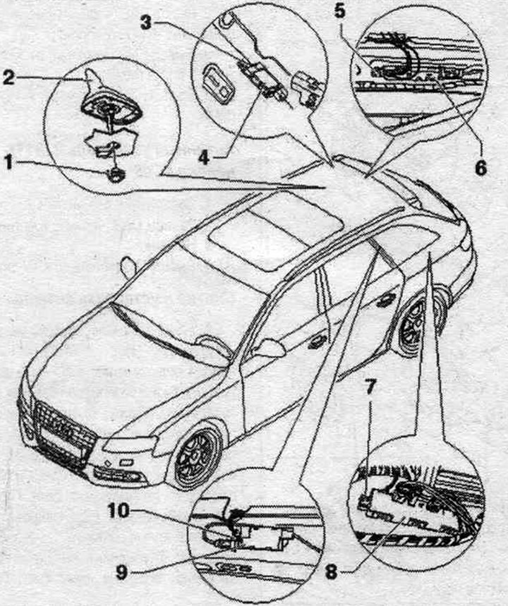
1. Nut: 6 Nm.
2. Antenna for radio, telephone, navigation. syst. "R52".
3/5/7/10. Bolt: 2 Nm.
4. Antenna amplifier 2 "R111".
6. Antenna amplifier "R24".
8. Antenna amplifier 3 "R112" (MMI up to calendar. weeks 44/08).
9. Antenna amplifier 3 "R112" (cAN/MMI radio with calendar, weeks 45/08). Antenna amplifier 4 "R113" (MMI)
Connectors
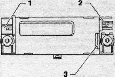
Antenna amplifier 3 "R112" (cAN radio)

1. Connector (yellow) AM/FM1 to radio "R". Connector FZV (gray) to the central control unit. syst. comfort "J393".
2. Not busy.
3. Connection for antennas on glass.
Antenna amplifier 3 "R112" (MMI from calendar week 45/08)
1. Connector (yellow) AM/FM1 to radio "R". Connector FZV (gray) to the central control unit. syst. comfort "J393".
2. Connecting the TUZ to the TV tuner "R78".
3. Connection for antennas on glass.
Antenna amplifier 3 "R112" (MMI until calendar week 44/08)
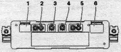
1. Connection for antennas on glass.
2. Output (yellow) FM2/FM3 from antenna amplifier "H24"/antenna amplifier 4 "R113".
3. TV1 output (green) to TV tuner "R78".
4. FZV connector (gray) to the central control unit. syst. comfort "J393".
5. High-frequency output HF/ZF (white) to the "R" radio.
6. Connection for antennas on glass.
Antenna amplifier 2 "R111"
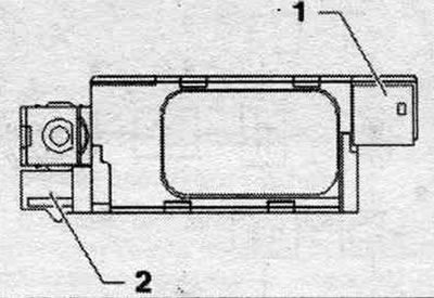
1. Connection for antennas on glass.
2. DAB output (black) to the "P" radio/digital radio "R147" (Europe).
Antenna amplifier "R24"
1. Connection for antennas on glass.
2. Connector (white) FM2 to the "R" radio (cAN radio).
Connector (purple) FM2/TV2 to antenna amplifier 3 "R112"/TV tuner "R78" (MMI until calendar week 44/08).
Connector (white/purple) FM2/TV2 to the "R" radio/TV tuner "R78" (MMI from calendars, weeks 45/08).
Antenna amplifier 4 "R113" (MMI until calendar week 44/08)
1. Output FM3 (purple) to antenna amplifier 3 "R112".
2. Output TV3 (green) to TV tuner "R78".
3. Connection for antennas on glass.
Antenna amplifier 4 "R113" (MMI from calendar week 45/08)

1. Not busy.
2. TV1 output (green) to TV tuner "R78".
3. Connection for antennas on glass.
Removal and installation the antenna amplifier 3 "R112" (MMI)
Antenna amplifier 3 "R112" is located behind the left trunk trim. Turn off the ignition. Open the left compartment in the luggage compartment. Unlock and disconnect the connectors "1", "2", "3", "4" and "5" of the antenna amplifier 3 "R112" "7". Unscrew the "arrow" bolts and remove the antenna amplifier 3 "R112" "7" from the side wall "6".
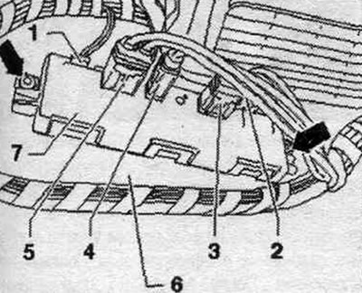
Installation in reverse order.
Removal and installation antenna amplifier 3 "R112" (SAN) / antenna amplifier 4 "R113" (MMI)
Antenna amplifier 3 "R112"/antenna amplifier 4 "R113" are located on pillar C on the left and right. The procedure for removal and installation is identical. Turn off the ignition. Remove the C-pillar trim. Unlock and disconnect plug connectors "1", "2" and "5" from the antenna amplifier 3 "R112" "4". Loosen the bolt "arrow" and remove the antenna amplifier 3 "R112" "4" from the C-pillar "6".
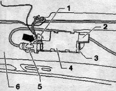
Installation in reverse order.
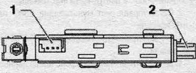
Removal and installation of the antenna amplifier "R24"
The antenna amplifier "R24" is located on top of the trunk lid. Turn off the ignition. Remove the rear trim. doors. Unlock and disconnect plug connectors "1" and "4-" from the antenna amplifier "R24" "2". Loosen the bolt "arrow" and remove the antenna amplifier "R24" "2" from the trunk "3".
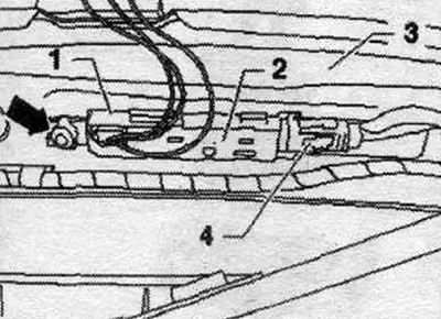
Installation in reverse order.
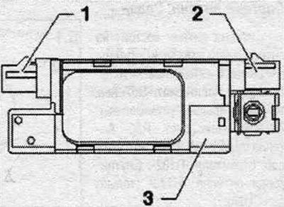
Removal and installation antenna amplifier 2 "R111"
Antenna amplifier 2 "R111" is located on the right D-pillar. Turn off the ignition. Remove the D-pillar trim. Unlock and disconnect plug connectors "1" and "4" from the antenna amplifier 2 -R111 - "2". Loosen the bolt "arrow" and remove the antenna amplifier 2 "R111" "2" from the D-pillar "3".
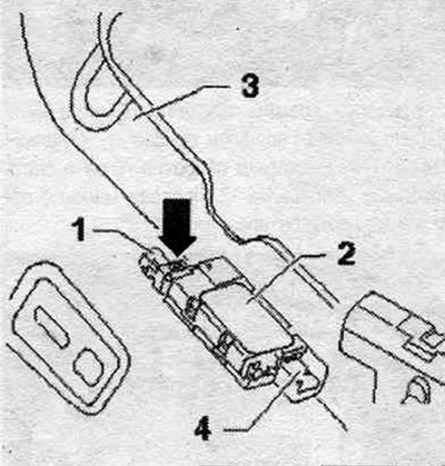
Installation in reverse order.
Removal and installation the roof antenna
Antenna for radio, telephone, and navigation system "R52" (GSM/GPS/RC/SAT) equipped with a maximum of 4 terminals. The antenna wires are mounted on the roof crossbar. To remove the antenna of the radio, telephone, and navigation system "R52", you should lower the rear ceiling panel down. Turn off the ignition. Lower the rear headliner. Unlock and disconnect plug connectors "1", "2" and "3" from the antenna wires. Disconnect the antenna wires of the radio, telephone, navigation system antenna "R52" "5". Unscrew the nut "4". Remove the radio, telephone, navigation system antenna "R52" "5" from the roof upwards.
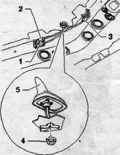
Installation
Route the antenna wires through the hole in the roof and carefully install the antenna for the radio, telephone, and navigation system "R52". Ensure the seal is correctly positioned. Installation in reverse order.