
Table of contents: Removal and installation the fairing ↓ Removal cover 1 of the sliding and… ↓ Removal cover 2 of the sliding and… ↓ Removal and installation the hatch… ↓ Removal and installation the sunshade ↓ Adjusting the parallelism of the… ↓ Removal and installation the sunroof… ↓ Avant drainage hoses ↓
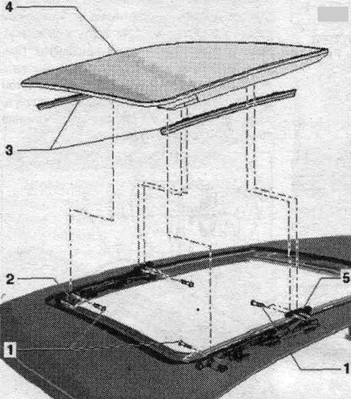
Lift-and-slide sunroof - Avant
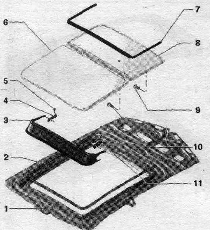
1. Hatch frame.
2. Gasket: To remove, open cover "1" completely and remove the gasket from the side; when installing, first place it in the front part, then insert it under the cover "2" from behind and press it along the perimeter on the sides to the flange.
3. Fairing.
4. Wind shield support.
5. Bolt: 1 Nm.
6. Cover "1".
7. Lid seal.
8. Cover "2".
9. Bolt: 3 Nm.
10. Bolt: 7 Nm.
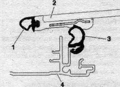
Removal and installation the fairing
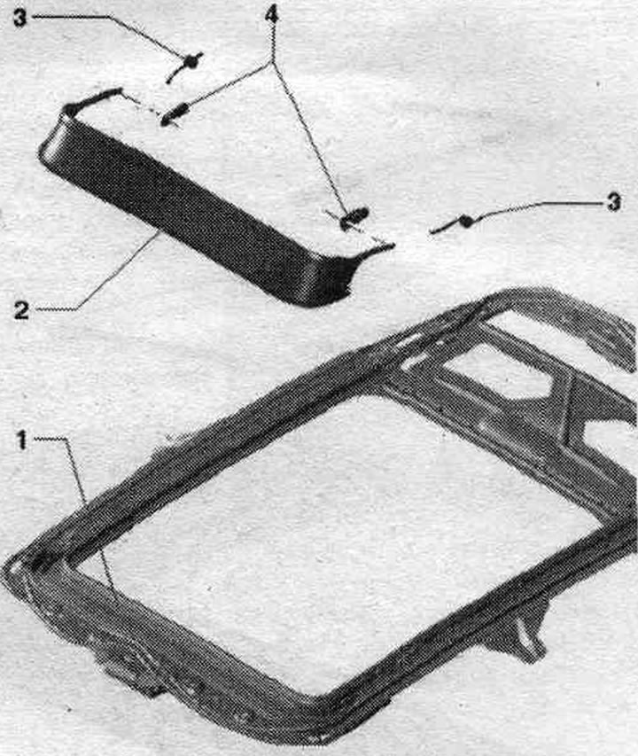
1. Hatch frame.
2. Fairing: to remove, open cover "1" and return it to the back, detach the fairing frame from the front of the clamping bar, starting from the side, lift the fairing and remove it from the side of the support.
3. Fairing spring.
4. Wind shield support.
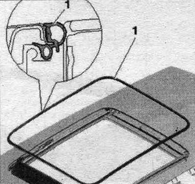
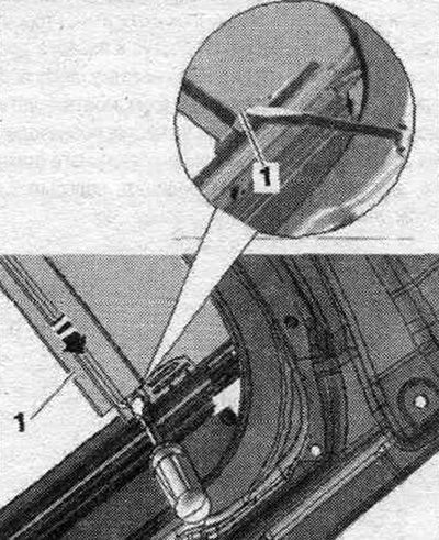
Detach the fairing from the frame
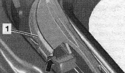
To remove, sequentially disconnect the fairing frame, starting from the side "arrow", from frame "1".
Replacing the fairing supports
Fairing "1" is removed. Unscrew bolt "3". Carefully press support "2" at the points marked with arrows, without damaging the paintwork, out of the groove and remove it from the side. To install, insert from the side, while the support is fixed in the groove.
Removal cover 1 of the sliding and lifting sunroof
When the cover is removed, do not move the mechanism, as this may cause damage. If the cover mounting bolts have been completely unscrewed. they should be replaced.
1. Bolt: front and back, 2 on each side; 7 Nm.
2. Guide linkage mount: not a spare part.
3. Lid cover: When removing the lid, pull it out from the lid backwards.
4. Cover 1: to remove, set the cover aside and remove the covers backwards, unscrew the rear bolts and slightly move the cover backwards, unscrew the front bolts and remove the cover upwards.
Removal cover 2 of the sliding and lifting sunroof
If the cover mounting bolts have been completely unscrewed, they should be replaced.
1. Bolt: 3 Nm.
2. Cover 2: To remove, fully open the sunshade and remove the soundproof seal on the side, unscrew the bolts on 2 sides at the front and back, and pull the cover up.
3. Cover seal: cover 2 is removed, remove the seal, starting from the side, left and right of the cover, remove the front. seal up from the lid; when installing, align the front center of the cover and press it into the guides, place the ends of the seal on the pins of the sprayers.
Adjusting the sliding sunroof cover
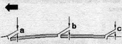
Arrow = direction of forward movement.
Size a = 1.5 mm.
Size b = 1.0 mm.
Size c = 0.5 mm.
All data ±0.5 mm.
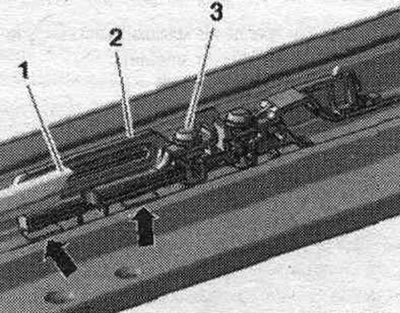
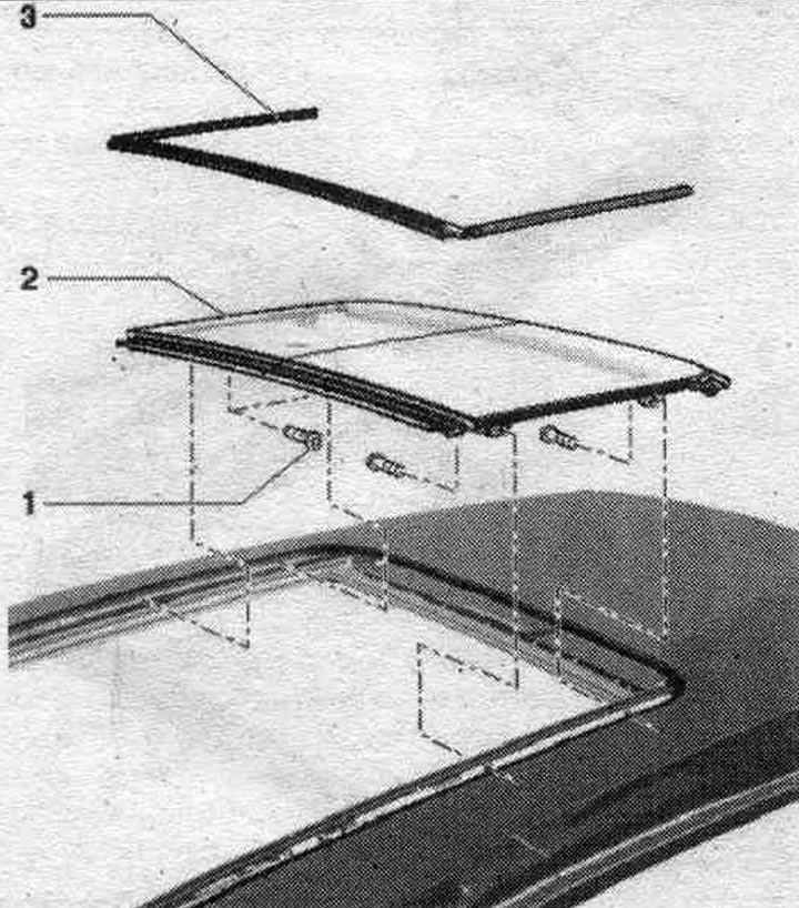
Installing the lid seal
Align the seal with the front center of the lid and press it into both guides.
Insert seal "1" from the side into the guides of cover "2". Removing seal "3" is only necessary when removing cover 2. To do this, remove "4" from the side of the frame.
Replacing the hatch seal
If necessary, remove any remaining adhesive from the body. Clean the adhesive surfaces of the body with cleaner -D 009 401 04-. The bonding surface must be free of dust and oil. Before gluing, heat the bonding surfaces and seal to approximately 40°C. After successful installation, press the seal with a pressure roller "3356". Before removing, remove both hatch covers. Pull off the seal -1 - from the side of the body flanging. If necessary, remove any remaining adhesive and clean the body flanging. Remove the protective film from the adhesive tape only on the back. side and press the seal by tapping from behind in the middle of the car (take into account the markings). Press the seal into the front radii. Press the seal to the front side. Press the seal against the longitudinal sides, stretching out any excess evenly if necessary. Press the seal along the perimeter with the pressure roller "3356".
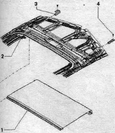
Removal and installation the hatch frame
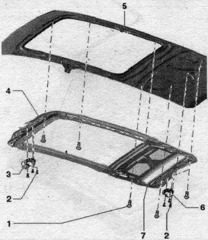
1. Bolt: 8 Nm.
2. Bolt: 3 Nm.
3. Used sliding hatch "J245": carry out adjustment pass.
4. Sunroof frame: removal: ceiling panel removed, disconnect plug connector, disconnect front and rear drainage hoses, unscrew bolts up to middle bolts - left and right, hold the frame with the help of technicians, only then unscrew middle bolts and slide the frame back out of the car; installation: Pre-fix the frame lightly with bolts, install the frame along the fixing holes using an 8 mm diameter drill at the front and rear, first tighten the front bolts, then the rear bolts across the frame with the appropriate torque, tighten the bolts in the longitudinal direction alternately on each side, starting from the rear and then the front, with the appropriate torque, put the front and rear water drain hoses on the frame. The side and middle bolts on the frame remain screwed in until the work is completed. Two technicians must hold the frame before removing the bolts and removing the frame.
5. Roof.
6. Used sun blind "J394": carry out adjustment pass.
7. Sunshade.
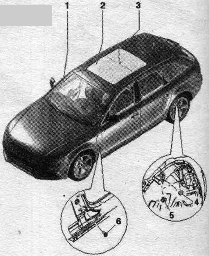
Frame attachment points
When installing, install frame "2" at the front right "arrow" near engine "1" using an 8 mm diameter drill and...
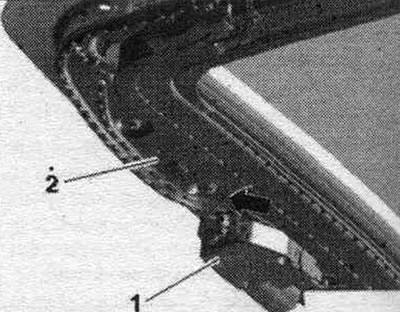
...at the back right (elongated hole) "arrow" next to engine "1" with a drill with a diameter of 8 mm.
Tighten the front bolts first, then the rear bolts across the frame to the correct torque. Tighten the bolts longitudinally, alternately on each side, starting from the rear and then the front, to the correct torque.
Sunshade
1. Sunshade: Remove the tab on the side of the sunshade fabric.
2. Sunshade Cable Catch: Replaceable with cable only.
3. Cover for cable traction.
4. Bolt: 1 Nm.
Removal and installation the sunshade
The sunshade panel is fully open. Frame and cover 2 removed. Secure the axle in the sun protection panel roller "1" to prevent twisting and tie it with wire "2".
Press the latch with a screwdriver and pull the curtain up.
Press the "arrow" lock down and insert the left shackle into the cable grip. On the opposite side, remove the bow from the grip and remove it from the side of the edging.
Use a small screwdriver to press the clamp upwards, as shown in the picture, and this will detach the fabric. Pull the curtain fabric back out of the frame and remove it with the curtain roller.
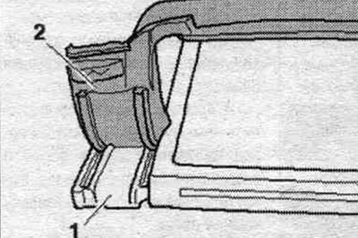
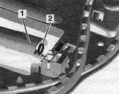
Install in reverse order, making sure the side reinforcement is inserted into the guide protrusions "1" of the frame part and passes under the guide protrusion "2". Remove the locking pin on the shaft only after inserting it into the frame. If the axle in the curtain shaft has been twisted, pre-tension can be created as follows. Before tensioning the curtain, first lightly tap the shaft to ensure that the spring is evenly stretched.
Screw in the axle of the deployed sun blind "1" until you feel a slight resistance. Then screw the axle in with the "arrow" tip by 12 turns with the shaft fixed and secure with the locking pin "2" or wire to prevent it from unscrewing.
After this, you can reinstall the sunshade.
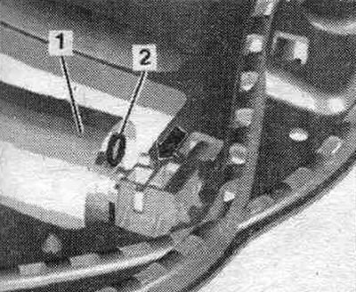
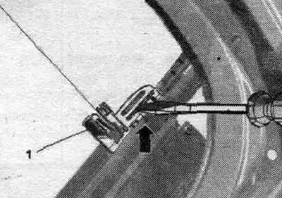
Replacing the sun protection panel cables
The sliding sunroof frame has been removed. The used sunshade "J394" has been removed. Unscrew bolt "2" and remove stop "1". Pull the cable back out of the frame. When installing, pay attention to the parallel movement of the grip.
Adjusting the parallelism of the cables
When installing, the new cables must be parallel. Insert the cables into the frame from both sides. Insert stop "1" and secure with a bolt. Push the cables in on both sides until they stop and install the used "J394" roof curtains. Perform an adjustment pass.
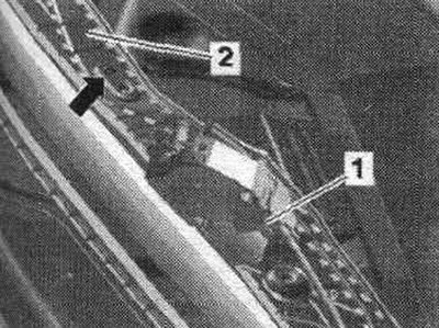
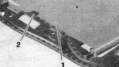
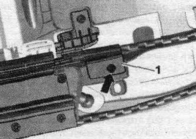
Adjusting the zero position of the cables
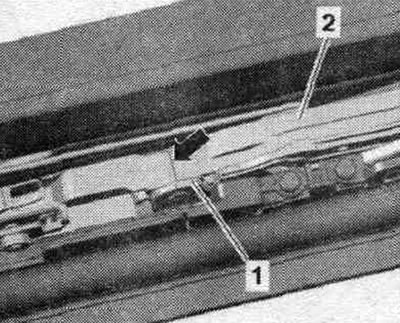
The hatch cover and engine have been removed. When adjusted correctly, the "arrow" marks on the guides of the "2" linkage and the "1" cover on the frame should be located on the same line. The used "J245" sunroof has been removed. If necessary, move the guides so that the marks are no longer visible.
Removal and installation the sunroof panel motor
After removing and installing the sunroof panel electric motor, it is necessary to check the original position of the cable rods and adjust them if necessary. The interior lighting cover has been removed. Disconnect the connectors. Unscrew the bolts (3 pcs.) and remove the engine from the opening in the ceiling. After installation, carry out a commissioning pass.
Removal and installation the sunshade motor
The ceiling panel has been removed. Disconnect the connectors. Unscrew the bolts (3 pcs.) and remove the engine from the frame. After installation, carry out a commissioning pass.
Engine adjustment pass
Perform adjustment work only with the cover removed, to avoid risk of damage. To ensure proper operation of the hatch, it is necessary to perform an engine adjustment run after the engine has been removed, installed or replaced.
Electric sunroof motor: Turn on the ignition and close the doors, close the sunroof if necessary. Pull out the sunroof control key and hold it in this position for 10 seconds. The hatch extends, moves back to the end position, then forward again and closes. During the entire adjustment process, the hatch control key must remain in the extended position. This completes the adjustment pass.
Electric sunshade motor: Turn on the ignition and close the doors, if necessary, close the sunshade completely. Press the curtain control key to the closed position and hold it in this position for 10 seconds. The curtain opens to its final position and then opens again. During the entire adjustment process, the curtain control key must remain inserted. This completes the adjustment pass. On new replaced engines, the adjustment run begins immediately after switching on, without waiting 10 seconds.
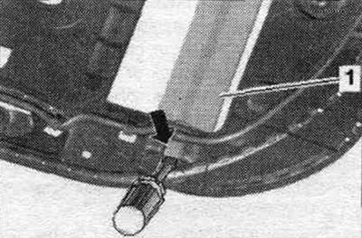
Avant drainage hoses
1. Front water drainage hose: removal: the front drainage hoses "1" pass through the A-pillars and end between the door and the A-pillar. To remove, remove the A-pillar trim at the top and bottom, remove the drainage hose from the sliding sunroof, disconnect the nozzle from the A-pillar and remove it downwards. Cleaning is performed from the opening of the sliding sunroof; installation: completely push the drain hose from below onto the A-pillar with an upward movement, press the nozzle against the A-pillar and insert the drain hose near the sliding hatch, fix the drain hose in the brackets near the A-pillar.
2. Lift-and-slide hatch.
3. Rear water drain hose: removal: the rear water drain hoses "2" pass through the C-pillars and end at the side under the fender liner, the C-pillar and D-pillar trim has been removed and the ceiling panel in the rear. area is lowered, removing the drainage hose from the rear. sliding sunroof; in the front area, detach the fender liner and push it to the side so that access to the drain hose nozzle is provided, detach the nozzle from the bottom of the fender liner and remove it with a downward movement; installation: installation in reverse order, they are cleaned from the lower end of the drainage hose, for this you should disconnect the fender liner in this place or press it to the side.
4. Cork: only in cars without a sunroof.
5. C-pillar attachment.
6. A-pillar bushing.