
Table of contents: Ignition coil/spark plug. Engine… ↓ Direct ignition ↓ Safety precautions when working with… ↓
The ignition system produces sparks that ignite the sucked-in fuel-air mixture. To do this, the ignition coils convert the 12 V voltage into 30,000 V.
In gasoline engines with electronic ignition, the control unit determines the ignition timing based on the ignition characteristic stored in its memory. The ignition system is synchronized by signals that come to the control unit from the Hall sensor or pulse sensor. The presence of anti-knock control ensures the economy of engine operation at a high compression ratio and compensation for differences in fuel quality characteristics. The knock sensor on the cylinder block registers the occurrence of detonation during fuel combustion and initiates the engine control unit to shift the ignition in the "late" direction. This ensures smooth engine operation and the absence of damage from detonation. Some engines have two knock sensors on the cylinder block.
Ignition coil/spark plug. Engine 2.0L ALT
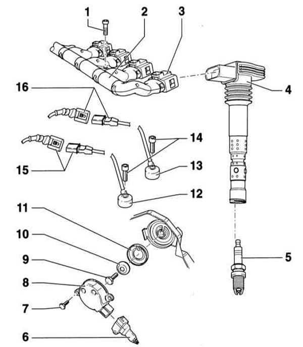
- 1 - Screw
- 2 - Plug strip
- 3 - Connecting plug
- 4 - Ignition coil with output stage
- 5 - Spark plug, 30Nm
- 6 — Connecting plug
- 7 - Bolt, 10Nm
- 8 — Hall sensor
- 9 - Bolt, 25Nm
- 10 - Washer, conical
- 11 — Hall sensor cover. When installing, pay attention to the fixation.
- 12 — Knock sensor 1
- 13 — Knock sensor 2
- 14 - Screw, 20Nm. Be sure to follow the tightening torque precisely, as this will affect the operation of the knock sensor.
- 15 — Three-pin green connector of the knock sensor 1. Mounted on the front wall of the engine compartment on the left in the direction of travel, under the expansion tank
- 16 — Three-pin green connector of knock sensor 2. Mounted on the front wall of the engine compartment on the left in the direction of travel, under the expansion tank
Direct ignition
The distribution of ignition current to the spark plugs is controlled by the electronic control unit.
The 1.6 and 2.4 L petrol engines have 2 or 3 ignition coils located in the same housing with the output stage on the cylinder head. Each ignition coil supplies voltage to 2 spark plugs. Some engines have 4, 6 or 8 ignition coils located directly on the spark plugs. In this case, the ignition cable is missing.
External adjustment of the ignition timing is not performed. If the ignition timing deviates from the specified value, it is necessary to replace the damaged elements.
The ignition system does not wear out and does not require maintenance. According to the maintenance schedule, only the spark plugs need to be replaced.
Basic information on the operation and sensors of the control and injection systems is presented in Section Functioning of the control and injection system of a gasoline engine.
Safety precautions when working with the ignition and injection system
To avoid injury to people and/or damage to the injection and ignition system, the following must be observed:
- Do not touch or disconnect spark plug wires while the engine is running or the starter is engaged.
- Disconnect and connect injection system pipes and ignition wires, as well as electrical wires of measuring devices only with the ignition switched off.
- Do not allow people with a pacemaker to work on the electronic ignition system.
- Terminal 1 of the ignition coils must not be shorted to ground.
- When turning the engine over with the starter, for example when checking the compression pressure, turn off the ignition and disconnect the crankshaft position sensor connector.
- Do not connect the test lamp to terminal 1 of the ignition coils.
[The article was copied from the website: audimanual.ru]