
Table of contents: Removal ↓ Electric motor for glass heating… ↓ Electric motor for driving the right… ↓ Central flap drive motor ↓ Electric motor for driving the left… ↓ Checking the electric motor ↓ Installation ↓
The ventilation flaps are driven by an electric motor. All electric motors are mounted in the same way on the heater/air conditioner box. To access the installation site, it is necessary to remove various covers. For easier orientation, the electric motors are painted in different colors.
Warning: After installation, the electric motors must be matched with the control unit. The service station has a special diagnostic device for this purpose.
Removal
1. Disconnect the negative (-) battery cable.
Follow the instructions in Section Replacing the battery.
2. Remove the glove box, refer to Section Removal and installation the glove box.
Electric motor for glass heating flap drive
1. Disconnect the connector (A) and remove the screws (B).
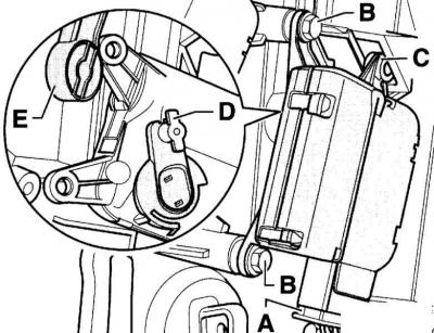
2. Disconnect the electric motor from the holder (C).
3. Disconnect the motor lever (D) from the connecting rod.
Electric motor for driving the right air temperature control flap
1. Disconnect the connector (A) and remove the screw (B).
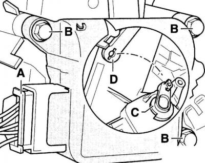
2. Disconnect the motor lever (C) from the connecting rod (D) and remove the motor.
Central flap drive motor
1. Remove the pocket from the driver's side, refer to Section Removal and installation the pocket on the driver's side.
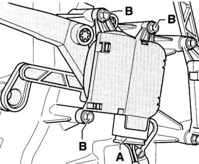
2. Disconnect the connector (A), unscrew the screw (B) and remove the electric motor.
Electric motor for driving the left air temperature control flap
1. Disconnect the connector (A) and remove the screws (B).
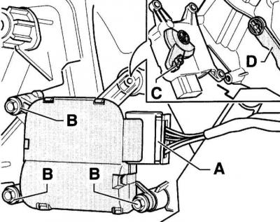
2. Disconnect the motor lever (C) from the connecting rod (D) and remove the motor.
Checking the electric motor
To test the electric motor, it is necessary to make a special cable.
1. Use plug (A) AUDI 8D0 972 706. Connect wires with a cross-section of 0.25 mm² to contacts (5) and (6). Connect regular crocodile plugs (B) to the other ends of the wires.
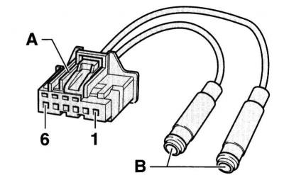
2. Connect the plug to the electric motor and the alligator clip to a 12 V DC source. The electric motor should move to the stop. When the polarity changes, the direction of rotation should change.
Installation
1. Install the electric motor so that the journals (A) and (C) fit into the groove of the cam washer (C).
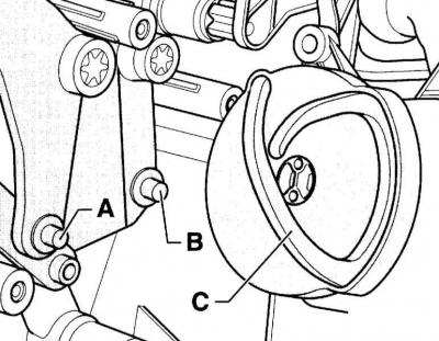
Warning: The accompanying illustration shows the central flap drive motor.
2. Route the wiring harness so that it does not come into contact with moving parts, such as the electric motor lever.
3. Further installation is carried out in the reverse order of removal.
4. Connect the negative (-) battery cable.
Warning: Follow the instructions in Section Replacing the battery.
5. Perform basic setup using the diagnostic tool. Read the information from the fault memory and then erase it (work of the service station).