
The engine's drive force is transmitted via two hinge shafts. Each shaft is connected to the wheel and the main transmission via two constant velocity joints.
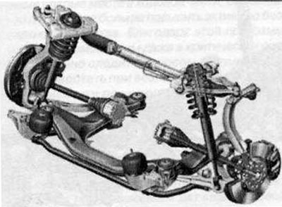
Front axle: Lightweight four-link axle with virtual kingpin axis together with front tubular anti-roll bar forms the structure for the wheel suspension guide system
Optimal handling and low tyre wear can only be achieved with perfect wheel alignment. In case of abnormal tyre wear and insufficient road holding, contact a workshop to have the wheel alignment measured.
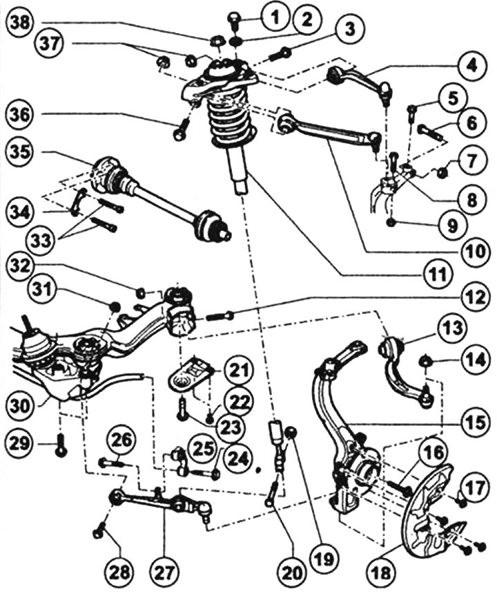
Front axle details: 1 - Hexagon head bolt 75 Nm, 2 - washer, 3 - Hexagon head bolt (replace after dismantling), 4 - upper rear suspension arm, 5 - hexagon head bolt 5 Nm, 6 - bolt, 7 - self-locking nut 50 Nm (replace after dismantling), 8 - hexagon head bolt, 9 - self-locking nut 40 Nm, 10 - upper front suspension arm, 11 - shock absorber strut, 12 - hexagon head bolt (replace after dismantling), 13 - lower suspension push rod(if the hydraulic support is leaking, replace it), 14 - self-locking nut 120 Nm (replace after dismantling), 15 - wheel bearing housing, 16 - hexagon head bolt (replace after dismantling; M14: 115 Nm + 180°, M16: 190 Nm + 180°), 17 - flange bolt 10 Nm, 18 - cover, 19 - self-locking nut 90 Nm (replace after dismantling), 20 - Hexagon head bolt, 21 - Bracket support, 22 - Hexagon head bolt 55 Nm, 23 and 24 - Hexagon head bolt 115 Nm + 90'(replace after dismantling), 25 - connection, 26 - hexagon head bolt 40 Nm + 90° (replace after dismantling), 27 - lower wheel suspension support arm, 28 - hexagon head bolt M12x1.5x85 (replace after dismantling), 29 - Hexagon head bolt, 30 - Front axle bracket, 31 and 32 - Self-locking nuts 70 Nm + 180° (replace after dismantling), 33 - multi-tooth screw (M8: 40 Nm, M10: 70 Nm), 34 - lining, 35 - hinge shaft, 36 - hex head bolt (replace after dismantling), 37 - self-locking nut 50 Nm + 90'(replace after dismantling), 38 - flange nut 60 Nm (replace after dismantling).
(The text is based on materials from the website: «Audimanual.ru»)