
Table of contents: Drive shafts ↓ Removal the quattro rear drive shaft ↓ Removal the outer hinge ↓ Removal the inner hinge ↓ Removal the inner hinge ↓
Drive shafts
Usually there are no problems with drive shafts. Their durability depends, of course, on the driving style of the car. Starting with the gas pedal fully depressed and the front wheels turned and starting with the front wheels turning lead to the appearance of a premature defect.
- Drive shaft joints often suddenly develop defects that then disappear completely. The "rest period" can last for several days and kilometers.
- When applying gas and changing gears, rhythmic beating or clicking sounds are characteristic. If these sounds also change depending on the steering wheel rotation, then the defect is probably in the joint on the wheel side.
- Vibration and shaking of the steering wheel when the wheels are turned also indicate a damaged outer joint.
You need a new flange bolt with a hex head for the outer joint shaft on the wheel hub, as it stretches when tightened and therefore should not be re-installed for safety reasons. Then a new gasket for the inner joint shaft (only in vehicles with a four-cylinder engine and manual transmission).
1. Remove the wheel cap or center cap on light metal rims.
2. Loosen the wheel bolts.
3. Loosen the hex bolt on the wheel hub; to do this, the Audi must be firmly on the ground.
4. Raise the front of the vehicle and secure it.
5. Remove the wheel.
6. If necessary, remove the drive shaft cover on the gearbox.
7. Remove the wire to the ABS speed sensor from the bracket, slightly pull the speed sensor back.
8. Remove the internal multi-tooth head shaft bolts on the gearbox.
9. Press the propeller shaft away from the flange on the drive side of the gearbox.
10. To remove the shaft, turn the steering wheel accordingly.
11. Installation: Place a new gasket on the inner hinge (only in vehicles with a four-cylinder engine and manual transmission). To do this, remove the protective film from the gasket.
12. First insert the drive shaft on the wheel side. Then cross-tighten the mounting bolts on the drive shaft flange on the gearbox side (M8 bolts: 40 Nm; m10 bolts: 77 Nm). Don't forget the shims in the homokinetic joints!
13. Lower the vehicle, block the wheels. Tighten the new axle hub bolt as shown below:
14. Bolt M14: tighten to 115 Nm and then another 1/4 turn (90°).
15. Bolt M16: tighten to 190 Nm and then another 1/4 turn (90°).
16. Manually push the ABS speed sensor back in until it stops.
Tip: Audi describes the removal of the shaft after removing the tie rod and both axle joint bearings. But we can remove the drive shaft - as described above - without unscrewing the wheel bearing housing (commonly known as "steering knuckle").
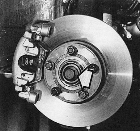
The arrow points to the outer joint center bolt, which must be removed when removing the drive shafts.
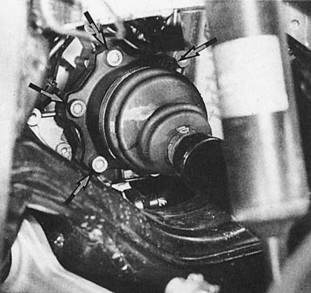
The inner joint is removed from the transmission by loosening the six internal multi-tooth head bolts (arrows). Shown here is a tripod joint on an automatic transmission.
Removal the quattro rear drive shaft
For assembly, you need a new hexagonal head combination bolt for the joint shaft on the outer side of the wheel hub. The old bolt cannot be reused for safety reasons. In addition, you need a new gasket for the inner joint shaft, a washer and a self-locking nut for securing the axle arm at the top, and a self-locking nut for the stabilizer connecting rod.
1. Remove the wheel cap or light metal rim trim in the middle.
2. Loosen the wheel bolts.
3. Loosen the hexagon head wheel bolt in the wheel hub; to do this, the Audi must be firmly on the ground.
4. Raise and secure the rear of the vehicle.
5. Remove the wheel.
6. To remove the left drive shaft, remove the intermediate muffler of the exhaust system (chapter Exhaust system).
7. Remove the internal multi-tooth head shaft bolts on the rear axle differential.
8. Slightly move the ABS speed sensor back.
9. Disconnect the stabilizer connecting rod mounting bolt from the wheel bearing housing (steering knuckle).
10. Unscrew the axle arm at the top from the wheel bearing housing (steering knuckle).
11. Press the cardan shaft away from the drive flange on the gearbox.
12. Remove the shaft.
13. Installation: Place a new gasket on the inner hinge. To do this, remove the protective film on the gasket.
14. Install the drive shaft first on the wheel side. Then tighten the mounting bolts crosswise on the drive shaft flange on the gearbox side (40 Nm). Do not forget the shims
15. Reassemble the axle suspension. First, tighten the screw connection of the wheel bearing housing and the axle arm by hand. Tighten the stabilizer connecting rod nut to 50 Nm.
16. Reassemble the exhaust system.
17. Lower the car. Block the wheels.
18. Tighten the new axle hub bolt as follows: tighten to 115 Nm and then tighten another 1/4 turn (90°).
19. Tighten the wheel bearing housing/axle arm screw connection finally with the vehicle standing on its wheels: 70 Nm and then another 1/4 turn (90°).
20. Manually push the ABS speed sensor back in as far as it will go.
Tips: Do not drive the car with the PTO shaft removed, otherwise the wheel bearing will be damaged. As a last resort, install only the outer PTO.
Depending on the engine and gearbox model, Audi uses different drive shafts. When purchasing a new part, have the engine and vehicle identification numbers with you.
Removal the outer hinge
For all models
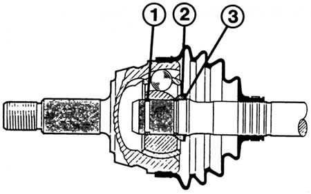
- 1 - retaining ring;
- 2 - spacer washer;
- 3 - disc spring.
1. Remove the drive shaft.
2. On a working cuff, bend back the large hose clamp and slide off the protective sheath.
3. If the cuff is damaged, replace it completely.
4. Using an aluminum or synthetic hammer, hit the joint hard from the inside to remove it from the shaft.
5. Before installing the new joint, insert a new snap ring into the groove of the drive shaft.
6. Install the disc spring and spacer washer - if installed on this version of the drive shaft - as shown in the picture above. Do not forget to install the rubber cuff.
7. When installing, hammer the joint onto the shaft with a synthetic hammer so that the retaining ring fits into the groove.
8. Lubricate the joint: 90 g of MoS2 grease (VW G6) is pressed into a new joint with an outer diameter of 89 mm, of which 40 g is pressed into the joint and 50 g into the cuff.
9. More grease is placed in the joints with an outer diameter of 98 mm: 120 g of MoS2 grease (VW G6) is distributed as follows: 80 g in the joint and 40 g in the cuff.
10. For used joints, grease is only added.
11. Firmly tighten the cuff clamps.
Removal the inner hinge
Homokinetic hinges
- 1 - retaining ring;
- 2 - internal homokinetic hinge;
- 3 - drive shaft.
1. Remove the drive shaft.
2. With patience, use two narrow screwdrivers to remove the retaining ring that holds the joint on the drive shaft from the groove at the end of the shaft.
3. Now remove the drive joint from the shaft; as a last resort, help yourself a little with a plastic or aluminum hammer.
4. If the joint cannot be removed in this way, it must be pressed off the shaft in the workshop using a repair press.
5. When installing, first place the cuff.
6. In the version with a disc spring, before installing the joint, slide the disc spring onto the shaft or check its position: it should be convex towards the joint along the outer edge.
7. Slide the joint onto the shaft and install the retaining ring.
8. This way the snap ring will not move into the groove. Therefore, clamp the drive shaft in a vice, place a large screwdriver or piece of pipe against the inside of the joint and hit the screwdriver hard with a hammer.
9. Counteracting the force of the disc spring, the hinge will move back a little - the retaining ring will be able to jump into the groove.
10. Lubricate the joint: press 80 g of MoS2 grease (VW G6) into a new joint with an outer diameter of 100 mm, of which 30 g into the joint and 50 g into the cuff.
11. More grease goes to the joint with an outer diameter of 108 mm: 120 g of MoS2 grease (VW G6) is distributed as follows: 35 g in the joint and 85 g in the cuff.
12. For used joints, only add grease.
13. Before tightening the hinge (or flange cuff) lubricate the sealing surface between the cuff flange and the joint with VW D3 sealant.
Removal the inner hinge
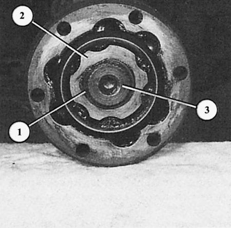
"Tripod" type joints
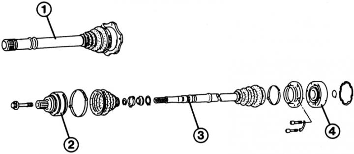
The tripod type joint (1) is not removed from the drive shaft. The situation is different with homokinetic joints, here the outer joint (2) and the inner joint (4) are removed directly from the drive shaft (3).
1. Tripod type joints are not removed from the drive shaft. They are sold as complete parts with the shaft and protective cuff. Therefore, when replacing, remove only the outer joint and replace the shaft with the inner joint.
2. If only the tripod protective cuff is defective, the outer shaft joint is dismantled. In this case, the cuff can be moved along the cleaned drive shaft to the tripod. Critical position: the cuff must be carefully lifted above the convex part in the middle of the shaft. To do this, lubricate the convexity and lift the cuff above the thickening with a blunt round tool (with a spoon handle).
3. The joint is filled with 140 g of grease G 000 605. When replacing the cuff in used joints, add grease.