
The clutch housing is bolted to the rear surface of the flywheel, and the driven disc is located between the pressure plate and the friction surface of the flywheel.
The disc hub has a splined connection with the gearbox drive shaft and can move freely along the splines. Friction linings are riveted to both sides of the disc, and its hub has damping springs that soften the impact energy and ensure smooth gear shifting.
When the clutch pedal is pressed, the slave cylinder pusher moves the clutch release lever forward, and the release bearing begins to press on the diaphragm spring fingers. As the center of the spring moves inward, its outer part moves outward and moves the pressure plate away from the driven one. Torque is no longer transmitted to the gearbox.
When the clutch pedal is released, the pressure plate, under the pressure of the diaphragm spring, sits on the friction linings of the driven disk and simultaneously pushes it forward slightly along the splines of the drive shaft of the gearbox until it engages the flywheel. The driven disk is clamped between the pressure plate and the flywheel, and torque begins to be transmitted to the gearbox
As the driven disk linings wear, the pressure plate at rest moves closer and closer to the flywheel, causing the diaphragm spring fingers to lift slightly. On a cable-actuated clutch, this would require some adjustment, but the hydraulically-actuated clutch found on the models in question does not require readjustment. Wear is automatically compensated for each time the clutch pedal is pressed by changing the amount of hydraulic fluid in the circuit.
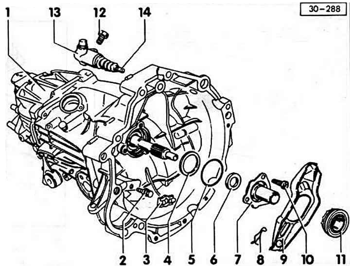
1 - gearbox
2 - spherical support
3 - spacer
4 - disc spring
The smaller diameter faces the guide bushing (convex side).
5 - oil seal
Replaced with a new one.
6 - drive shaft ring
7 - guide bushing
8 - spring retainer
9 - clutch release lever
10 - bolt, 25 Nm
11 - clutch release bearing
12 - bolt, 25 Nm
13 - clutch slave cylinder
When installing, press with a crowbar so that the mounting bolt can be installed.
14 - rod
Lubricate its end with thick grease.
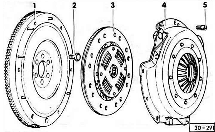
1 - flywheel
2 - flange bolt, 60 Nm +¼ turn (90°)
The turn can be done in two steps of 45° each. Always use a new bolt coated with locking agent.
3 - driven disk
4 - pressure plate
5 - screw, 25 Nm
[The article was copied from the website «audimanual.ru»]