
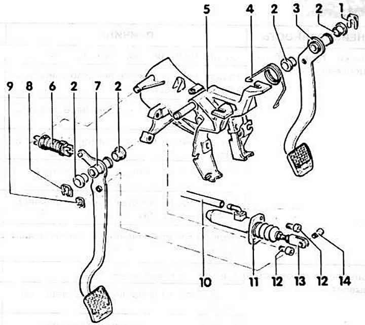
1 - stopper
2 - bearing sleeve
Pressed, press in a vise.
3 - brake pedal
4 - return spring
5 - pedal support
6 - spring
7 - clutch pedal
8 - stopper
9 - stopper
10 - hose
11 - clutch master cylinder
12 - bolt, 20 Nm
13 - fork of the clutch pusher rod
Install so that the clutch pedal is 10 mm higher than the brake pedal. Make sure that the spring returns the pedal to its original position and the pedal in it does not touch the support. Otherwise, friction linings wear out quickly.
Note: Lubricate all contact and friction surfaces in the joints with MoS paste2.
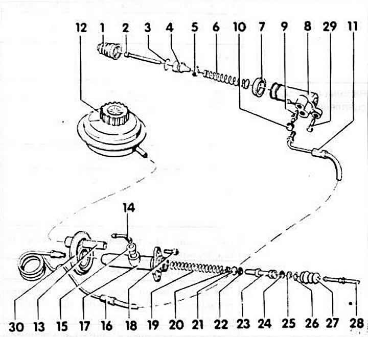
1 - anther
2 - pusher
The polymer part faces the clutch release lever.
3 - lock washer
4 - pistons
5 - U-shaped cuff (with groove) The sealing lip faces
to the spring.
6 - spring
7 - thrust washer
When installing the working hydraulic cylinder, lightly lubricate the outer working surface.
8 - working cylinder
9 - supply valve
10 - anther
11 - hose
12 - brake fluid reservoir
13 - hose
14 - fitting
15 - sealing plug
Moisten with brake fluid when installing.
16 - pipeline
17 - master cylinder
18 - bolt, 20 Nm
19 - spring
20 - puck
21 - primary cuff
Seal lip to spring
22 - puck
23 - piston
24 - secondary cuff
The sealing lip faces the spring.
25 - puck
26 - lock washer
27 - anther
28 - pusher
29 - bolt, 25 Nm
30 - holder
Visitor comments