
Table of contents: Removal ↓ Installation ↓
Removal
Observe safety precautions when disconnecting the battery terminals. The battery is located in a special compartment in the trunk. Turn off the ignition and remove the key from the ignition switch. Disconnect the ground cable "arrow" from the battery. Remove the engine hood.
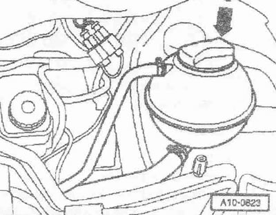
Attention! When opening the cap, hot steam or hot coolant may come out of the expansion tank, wrap the cap with a rag and carefully open the tank.
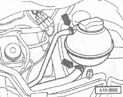
Open the "arrow" cap of the expansion tank.
Remove the noise insulation screen "arrows".
Place a tray for the VAS 6208 service cranes under the engine. Remove the lower coolant hose from the "arrow" radiator and drain the coolant.
Instructions: The detachable element between the pre-catalyst and main catalyst must not be bent more than 10°. Risk of damage!
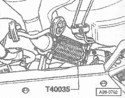
Support the detachable element using the "T40035" fixing device.
Unscrew bolts "2" on the pre-catalyst bracket.
Instructions. Ignore pos. "1". Mark the direction of rotation of the poly V-belt with chalk or a felt-tip pen. Changing the direction of rotation of a previously used belt may damage it.
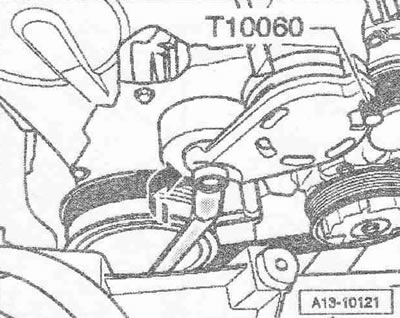
To loosen the poly V-belt, tilt the tensioner with a spanner "in the direction of the arrow". Secure the tensioner by installing the locking pin "T10060 A" or "T10060" in the locking holes. Remove the poly V-belt.
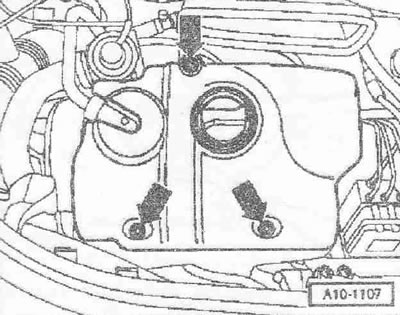
Remove the engine cover "arrows". Remove the noise insulation screen located below, to do this, disconnect the crankcase ventilation hose.
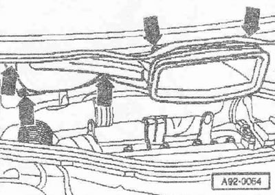
Using a screwdriver, remove caps "3" and "4" from the windshield wiper arms. Loosen the nuts on both arms a few turns. Release arms "1" and "2" by slightly tilting them on the windshield wiper axles. Loosen the nuts completely and remove the windshield wiper arms.
Disconnect the windshield washer fluid pipe "3". Disconnect the plug connectors "4" and "5" of the heated washer nozzles. Loosen the hose clamp "6" using the hose clamp pliers "VAG 1921" and remove the drain hose from the fairing grille. Remove the rubber seal "1" of the fairing grille. Remove the fairing grille "2".
Unscrew the bolts and nuts of the "arrows". Remove the fresh air intake duct and hang it on the right side of the car.
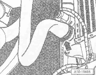
Loosen the nuts of the "arrow" threaded connection of the pre-catalyst with the turbocharger.
Disconnect the pre-catalyst from the turbocharger. Tie the pre-catalyst to the body.
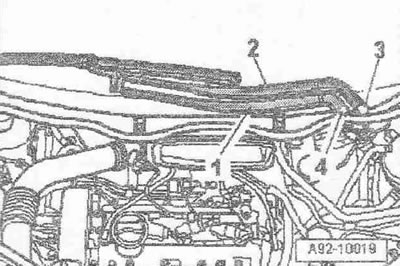
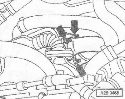
Disconnect plug connector "2" of air flow meter "G70". Disconnect vacuum hose "1". Release hose clamp "4" and remove air duct with air flow meter "G70". Unscrew nut "3".
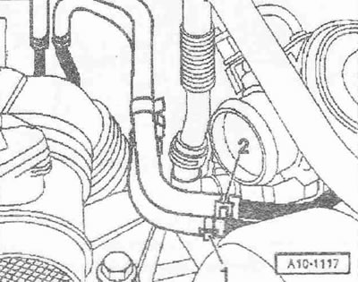
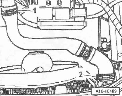
Remove air hose "2" connecting the intercooler and intake manifold. Ignore item "1".
Warning! The temperature of the fuel lines or fuel in vehicles equipped with a unit injector engine can reach 100°C. Allow the fuel to cool before disconnecting the fuel lines, otherwise severe burns may occur.
Mark and disconnect the fuel pressure line "2" and the fuel return line "1".
Mark the position of the supply hose "1" and the drain hose "2" in relation to the heater heat exchanger and remove the hoses from the front wall of the body.
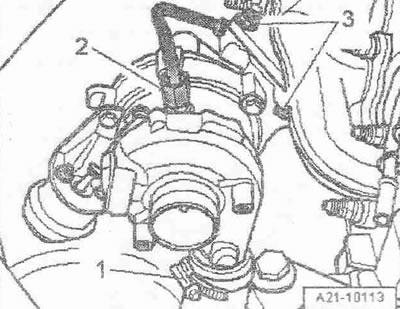
Unscrew the "arrow" bolts and remove the air duct from the turbocharger.
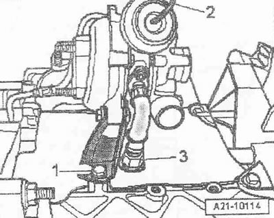
Remove air hose "1" from turbocharger. Unscrew pressure oil line "2" from turbocharger. Ignore item "3".
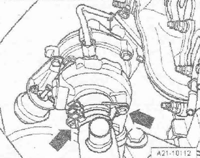
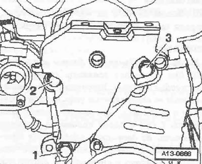
Remove the vacuum hose "2" from the boost pressure vacuum regulator and release it. Unscrew the oil return line "3" from the cylinder block. Unscrew the turbocharger support "1" from the cylinder block.
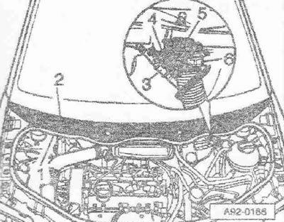
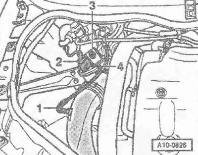
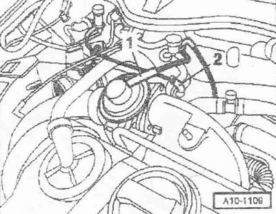
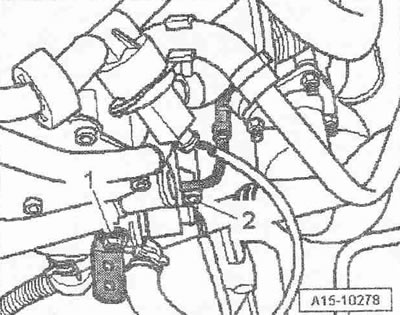
Disconnect vacuum hose "1" from brake booster. Disconnect plug connector "2" of fuel temperature sensor "G81" and release wiring. Disconnect plug connector "3" of coolant temperature indicator sensor "02" / coolant temperature sensor "662".
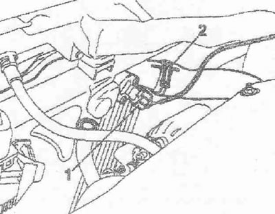
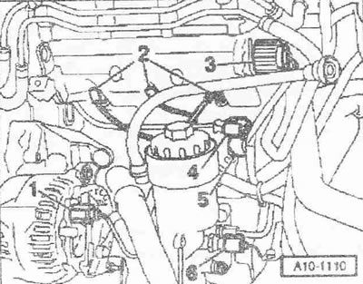
Disconnect vacuum hose "1" from mechanical EGR valve. Remove vacuum hose "2" from throttle control valve "N₂11".
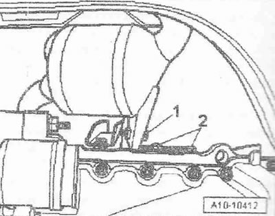
Disconnect the glow plug connectors "2". Remove the pin and loosen the nut with notch "3" on the central connector of the pump-injectors. Disconnect the connector "4" of the Hall sensor "G40" and remove the plug connection from the bracket. Ignore pos. "1, 5, 6".
Remove the upper coolant hose from the expansion tank -upper arrow-
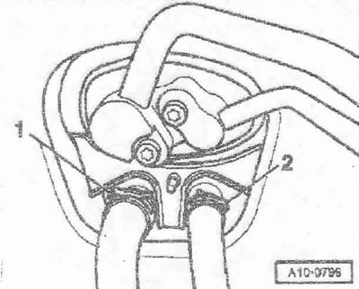
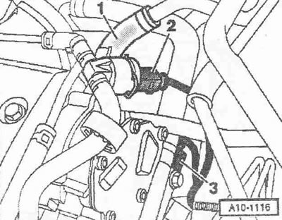
Remove the upper left coolant hose from the coolant pipe at the point marked with the number "1". Ignore item "2".
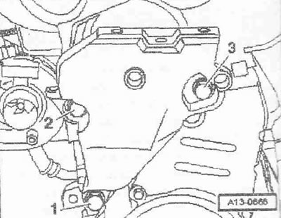
Unscrew the bracket "arrow" of the upper wiring harness from the coolant pipe. Unscrew the bracket "2" of the pressure oil line located below the coolant pipe from the turbocharger.
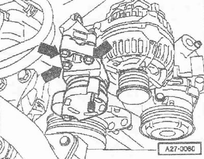
Unscrew the poly V-belt tensioner "arrow".
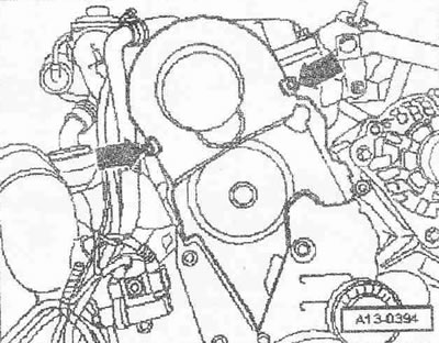
Remove the top cover of the gear belt by loosening the locking brackets "arrows".
Loosen the damper while holding the central bolt with a spanner.
Unscrew the middle and lower covers of the toothed belt "arrows".
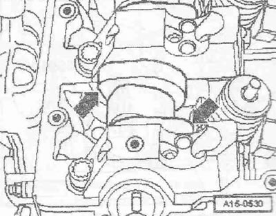
Remove bolt "1" of the engine support. Bolts "2" and "3" will be removed later.
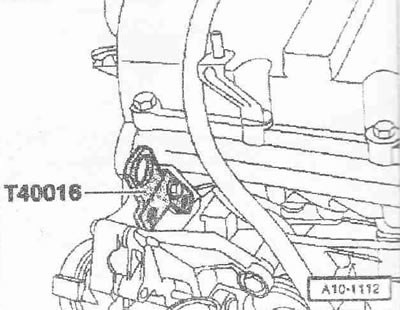
Screw the front right cargo eye "T40016" to the cylinder head.
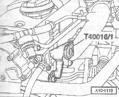
Screw the rear left cargo eye "T40016/1" to the cylinder head.
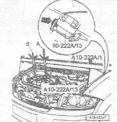
Install the crossmember "10-222 A" with the adapters "10-222 A/13" and 2 lead screws "A" and "8" on the connecting edges of the wings. The lead screws of the crossmember are facing forward. The additional right lead screw "B" is not used yet.
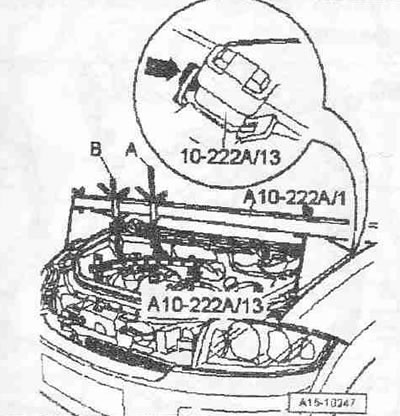
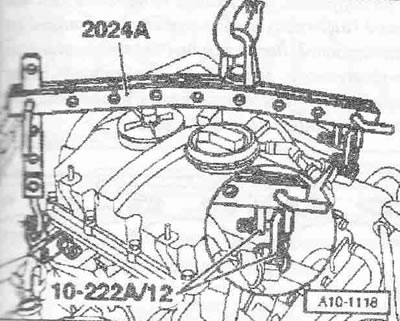
Install 2 "10-222 A/12" earrings on the rear left cargo eye "T40016" on the cylinder head. Fasten the "2024 A" hanging device to the engine and to the lead screw "A" of the "10-222 A" crossmember, as shown in the figure.
Instructions. To align the center of gravity of the power unit, the hook bars must be inserted as shown in the figure. The hooks and locking pins of the hanging device must be secured with cotter pins.
Tighten the engine on the lead screw without lifting the engine. Unscrew nut "3" when replacing the engine mount. Unscrew bolts "1" and "2" and remove the bracket with the engine chain.
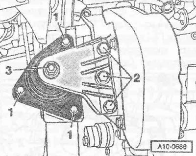
Unscrew bolts "2" and "3" and remove the engine support.
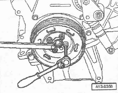
Caution! The engine may only be turned by the crankshaft in the direction of engine rotation (clockwise). To rotate the engine shaft, install the center bolt on the crankshaft.
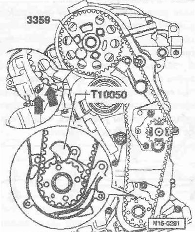
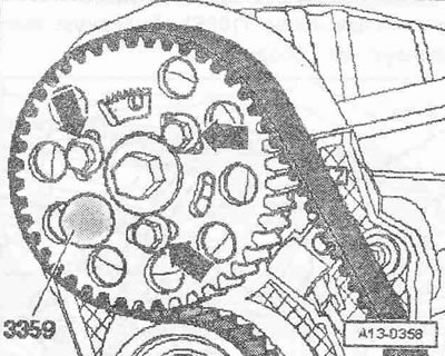
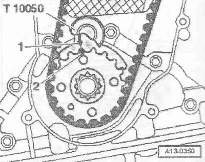
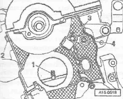
Bring the crankshaft to the TDC position of the first cylinder. The arrow on the rear cover of the toothed belt should point to the toothed ring of the hub "arrow". Fix the camshaft hub using the locking pin "3359". Fix the crankshaft gear using the crankshaft stopper "T10050".
Instructions: The stopper should be installed on the toothed belt pinion only from the end face of the toothed rim.
The marks on the toothed belt gear and the crankshaft stopper "T10050" must be opposite each other. The journal of the crankshaft stopper "T10050" must enter the hole of the sealing flange.
Mark the direction of rotation of the toothed belt with chalk or a felt-tip pen. Unscrew the bolts "arrows" of the camshaft gear.
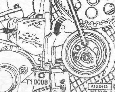
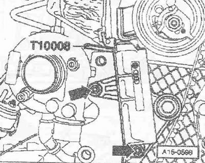
Insert the Allen key into the Allen hole until it stops and turn the tension roller counterclockwise "arrow" until the tensioner is locked with the locking plate "T10008".
Instructions: To avoid damage, insert the Allen key until it stops. The timing belt tensioner is equipped with an oil stop, so it can only be compressed gradually and with uniform force.
Loosen the tension roller fastening nut.
Unscrew the bolts "arrows" and remove the toothed belt tensioner. Remove the toothed belt. Remove the locking pin "3359".
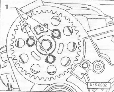
Unscrew the "arrow" bolts and remove the camshaft gear from the hub.
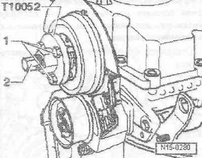
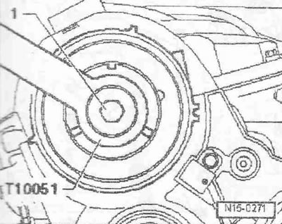
Loosen bolt "1" of the hub, holding it with the support "T10051". Unscrew the bolt by about 2 turns.
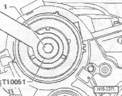
Place the puller "T10052" on the hub and screw in bolts "1". Remove the hub from the camshaft, holding the puller's hexagon with a 30 key and screwing in bolt "2". Remove the hub from the camshaft cone.
Remove the timing belt tension roller. Unscrew bolts "2... 4". Unscrew stud "1" with two M8 lock nuts.

Screw the bracket "T10014" into the threaded hole above the coolant pump.
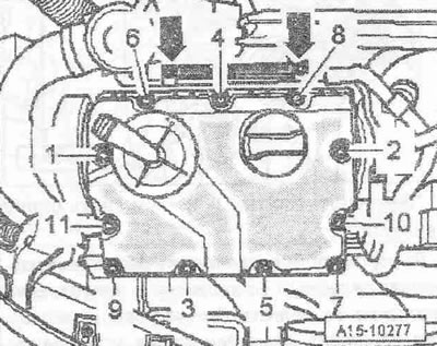
Fasten the lead screw "B" of the crosshead "10-222 A" to the bracket "T10014" Tighten the engine on the lead screw "B" until the load is removed from the lead screw "A". Fasten the hanging device "2024 A" to the engine. Put aside the hanging device "2024 A" and lead screw "A". Unscrew the bolts "arrows" of the fuel line bracket on the cylinder head cover. Unscrew the cylinder head cover bolts in the sequence "11...1". Remove the bracket together with the fuel lines. Remove the cylinder head cover.
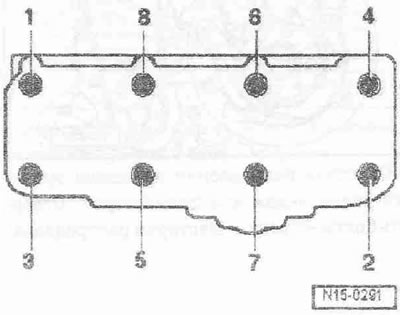
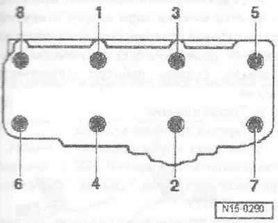
Loosen the cylinder head mounting bolts in the sequence "1... 8". Carefully remove the cylinder head. Place the cylinder head on a soft pad, with the combustion chamber side facing up.
Installation
Instructions. Replace the cylinder head mounting bolts. Replace the self-locking nuts and bolts during installation. Replace the bolts tightened to a certain angle, as well as the cuffs and gaskets. During repairs, carefully remove any remaining sealant from the cylinder head and cylinder block. Avoid the formation of long scratches or burrs. Carefully remove any remaining emery and sanding material. There must be no oil or coolant in the blind holes for the cylinder head mounting bolts. Remove the new cylinder head gasket from the packaging immediately before installation. Handle the gasket with extreme care. Damage to the silicone layer and corrugated joints will result in loss of sealing. Cylinder heads with cracks between the valve seats can continue to be used without reducing the service life, if these are small cracks with a width of max. 0.5 mm. Additional processing of the cylinder head is prohibited. When installing a cylinder head from the exchange stock with an installed camshaft, the mating surfaces between the hydraulic tappets and the cam bed must be lubricated with engine oil after installing the head. The plastic linings included in the repair kit for protecting open valves may be removed immediately before installing the cylinder head. Use clamps of the appropriate series to secure all hose connections. Replace contaminated oil. When replacing the cylinder head or cylinder head gasket, drain the old coolant and fill it with new coolant. After working with the valve mechanism, turn the engine by hand at least 2 revolutions to make sure that no valve is in contact with the piston.
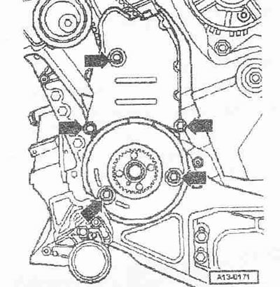
Check whether the camshaft and crankshaft are in TDC: the cams of the first cylinder should be facing up "arrows".
The crankshaft gear must be locked using the crankshaft stopper "T10050". The marks on the toothed belt gear and the crankshaft stopper "arrow" must be opposite each other. In this case, the stopper journal must enter the hole of the sealing flange.
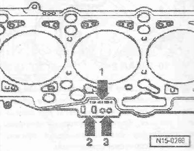
Observe the markings on the cylinder head gasket.
- 1. Parts catalog number
- 2. Control code (do not take into account)
- 3. Holes
Instructions. When replacing the cylinder head gasket or the cylinder head itself, use a gasket with the same marking. After replacing parts of the crank mechanism, it is necessary to again determine the parameters of the new cylinder head gasket based on the piston protrusion at TDC.
Install the cylinder head gasket. Make sure the centering bushings are present in the cylinder block. Observe the installation position of the cylinder head gasket, the "oben" mark or the part number must face the cylinder head. Install the cylinder head. Make sure that all the washers for the cylinder head mounting bolts are present in the cylinder head. Insert new cylinder head mounting bolts and tighten them. Tighten the cylinder head mounting bolts in 4 steps in the specified sequence: 1. Tighten with a torque wrench to 40 Nm. 2. Tighten with a torque wrench to 60 Nm. 3. Tighten further with a wrench by 90°. 4. Tighten further with a wrench by 90°. It is not necessary to tighten the cylinder head mounting bolts after carrying out repair work.
Lubricate bolts "2...4" with thread varnish and tighten. Tighten stud "1" with two M8 lock nuts.
Place the hub on the camshaft. Tighten bolt "1", holding it with support "T10051".
Install the camshaft gear onto the hub. The "arrow" toothed segment of the camshaft gear should be at the top.
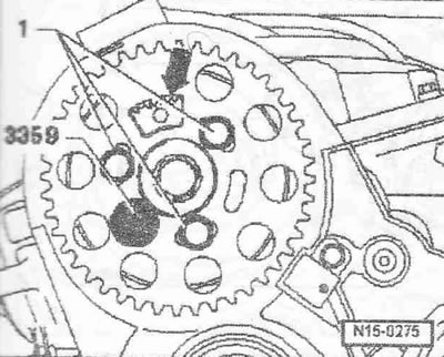
Do not screw in the bolts completely. Secure the camshaft hub with the locking pin "3359". Further installation is carried out in the reverse order, install the cylinder head cover. Install the toothed belt (adjust valve timing). Follow all instructions for removing and installing the toothed belt. The hoses and pipes of the air boost system must be cleaned of oil and grease before installation. Do not use lubricants under any circumstances. Install the torsional vibration damper. Install the poly V-belt. Install the bracket with the engine mount. Install the pre-catalyst with the main catalytic converter. Observe safety precautions when disconnecting the battery terminals. Install and adjust the windshield wiper arms. Check the oil level. Replace the coolant.
Tightening torques:
- Hall sensor "G40" to cylinder head: 10 Nm 1)
- Rear cover of the timing belt to the cylinder head M6: 10 Nm 1), M8 20 1)
- Cylinder head stud: 15 Nm
- Hub to camshaft: 100 Nm
- Engine support to cylinder block: 45 Nm
- Oil pressure line to oil filter holder: 22 Nm
- Return oil line to turbocharger: 15 Nm
- Upper coolant pipe to suspension eye: 20 Nm
- Turbocharger bracket to turbocharger: 20 Nm
- Turbocharger bracket to cylinder block: 20 Nm
- Return oil line to cylinder block: 30 Nm
- Wire harness bracket to coolant pipe: 10 Nm
- Bracket of pressure oil line to coolant pipe: 10 Nm
- Oil dipstick guide tube to oil filter holder: 10 Nm
- Guide tube of the oil dipstick to the hanging eye: 10 Nm
- Air duct to turbocharger: 8 Nm
1) Before installation, lubricate the bolts with thread varnish.
[The original material is located on the website: AudiManual]