Repair Chevrolet Repair Toyota Repair Honda Repair AvtoVAZ Repair Mercedes-Benz Repair BMW Repair Opel
Home  |  Contacts  |  Sitemap  |    
English Русский
Български
Беларускі
Український
Српски
Hrvatski
Română
Polski
Slovenský
Magyar
AudiManual.ru


  • AUDI 80
  • AUDI 100
  • AUDI A3
  • AUDI A4
  • AUDI A6
  • AUDI A8
  • AUDI Q
  • OTHER
  • ARTICLES
A2 (1999-2005)

Removal and installation of balance shaft and crankshaft frame (Audi A2)

  • Home
  • Audi
  • A2 (1999-2005)
  • Engine 1.2 l (diesel)
  • Engine repair
  • Removal and installation of balance shaft and crankshaft frame
            0
Table of contents: Removal ↓ Installation ↓

Removal


Remove the poly V-belt. Remove the toothed belt. Remove the oil pan. Remove the front sealing flange.

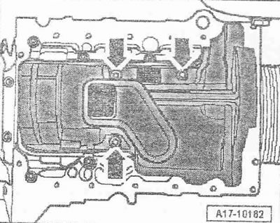
Unscrew the "arrow" bolts. Unlock the 5 fasteners and remove the oil separator.

Press the chain tensioner and secure it with the locking pin «T10060 A» or «T10060» «arrow».…


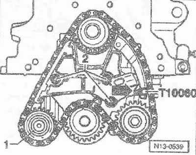
Press the chain tensioner and secure it with the locking pin "T10060 A" or "T10060" "arrow". Unscrew the freewheel sprocket "1" from the crankshaft frame. Unscrew the bolts "2" of the chain tensioner and remove the tensioner. Remove the chain from the sprockets and place it on a clean surface.

Fix the balance shaft with a 24/27 spanner, pos. «1», as shown in the figure. The spanner should be…


Fix the balance shaft with a 24/27 spanner, pos. "1", as shown in the figure. The spanner should be aligned coaxially with the counterweight, setting it at a right angle to the balance shaft. Loosen bolt "2" on the counterweight using the "T10061" attachment.


Instructions: Do not unscrew the bolt, just loosen it.


Unscrew the crankshaft frame «3» from the cylinder block and remove it together with the…


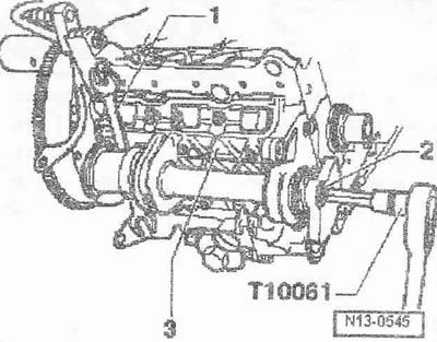
Unscrew the crankshaft frame "3" from the cylinder block and remove it together with the counterweight. Place the frame on a clean surface. Unscrew the bolt on the counterweight and remove the counterweight and sprocket. Turn the balance shaft so that it can be removed from the supports.

Installation


Installation is in the reverse order, while observing the following: Replace the sealing ring.…


Installation is in the reverse order, while observing the following: Replace the sealing ring. Replace the bolts tightened to a certain angle. Lubricate the working surfaces of the supports and install the balance shaft. Install the sprocket and counterweight on the balance shaft. The sprocket and counterweight are installed in one position only. Screw in the counterweight/sprocket bolt all the way. Before installing the crankshaft frame, make sure that the cylinder block centering sleeve and the sealing ring are present in the crankshaft frame. Screw the crankshaft frame to the cylinder block by hand and align it. The crankshaft frame on the belt pulley side must be flush with the outer edge of the cylinder block. Fully tighten the crankshaft frame bolts crosswise in several steps. Secure the balance shaft with a 24/2 7 mm wrench "pos. 2" as shown in the figure. The wrench should be aligned coaxially with the counterweight, installed at a right angle to the balance shaft. Screw the counterweight with a new bolt "2". Install the chain tensioner. Clean the chain with a rag. Make sure that the "arrow" mark on the crankshaft sprocket is at the top.


Install the chain on the crankshaft sprocket, oil pump sprocket and balance shaft sprocket. The…


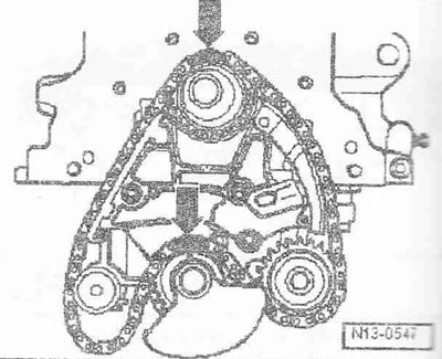
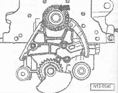
Install the chain on the crankshaft sprocket, oil pump sprocket and balance shaft sprocket. The marks on the crankshaft sprocket and balance shaft sprocket should be opposite the chain links marked with paint "arrows". The chain links marked with paint are additionally marked with a groove. Install the freewheel sprocket on the chain and screw the sprocket to the crankshaft frame. Remove the locking pin from the chain tensioner.

Make sure that the marks on the crankshaft sprocket and balance shaft sprocket are opposite the…


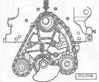
Make sure that the marks on the crankshaft sprocket and balance shaft sprocket are opposite the chain links marked with paint "arrows". Install the front sealing flange. Install the oil separator with a new sealing ring. Install the oil pan. Install the toothed belt (adjust valve timing). Install the poly V-belt.


Tightening torques:
  • Crankshaft frame with counterweight to cylinder block: 14 Nm + 180° 1)
  • Counterweight with sprocket to crankshaft frame: 100 Nm + 90° 1)
  • Chain tensioner to crankshaft frame: 8 Nm + 90° 1)
  • Freewheel sprocket to crankshaft frame: 20 Nm
  • Oil separator to crankshaft frame: 5 Nm

1) Replace the bolt
The article was checked by auto expert Daniil Ushakov
This article is available at russian, bulgarian, belarusian, ukrainian, serbian, croatian, romanian, polish, slovak, hungarian

Share information:
Previous articles
Audi A2: Engine repair
Next articles

Balance shaft and crankshaft frame — design description
Removal and installation the rear sealing flange
Removal and installation the front sealing flange
Replacing the crankshaft seal on the belt pulley side
Crankshaft — design description
Removal and installation the crankshaft sprocket
Removal and installation the cylinder head cover
Removal and installation of the cylinder head


Similar articles on other Audi car models:
Intermediate shaft — removal, inspection and installation Audi 80 B3 (1986-1991, petrol)
Removal, inspection and installation of the crankshaft Audi 100 C3 (1982-1990)
Removal and installation the shield and beam of the side… Audi A3 Type 8L (1996-2003)
Removal and installation the drive shaft Audi A4 B6 (2000-2006)
Removal and installation the drive shaft Audi A6 C5 (1997-2004)
Removal and installation the outer joint of the drive shaft Audi A8 D2 (1994-2002)
Removal and installation of timing chains, balance shaft and… Audi Q7 Typ 4L (2005-2015, diesel)
Link to this page in different formats


Visitor comments

No comments yet


How much will 23 + 44 =


Audi A2(1999-2005) 
  • General information
  • Introduction to the guide
  • Maintenance
  • Engine 1.4 l (gasoline)
  • Engine repair
  • Lubrication system
  • Cooling system
  • Exhaust system
  • Engine 1.6 l (gasoline)
  • Engine repair
  • Lubrication system
  • Cooling system
  • Exhaust system
  • Engine 1.2 l (diesel)
  • Engine repair
  • Lubrication system
  • Cooling system
  • Injection and turbocharging
  • Engine 1.4 l (diesel)
  • Engine repair
  • Lubrication system
  • Cooling system
  • Turbocharging system
  • Supply system
  • Fuel injection system
  • Exhaust system
  • Transmission
  • Mechanical gearbox 02J
  • Mechanical gearbox 02T
  • Mechanical gearbox 085 DS
  • Chassis
  • Car suspension
  • Steering
  • Brake system
  • Body
  • Exterior
  • Interior
  • Seats
  • Doors, locks and windows
  • Safety system
  • Heating and air conditioning
  • Electrical equipment
  • Power devices
  • Equipment and devices
  • Wipers and washers
  • Lighting and lamps
  • Breakers and switches
  • Electrical circuits
 
AudiManual.ru © 2017-2026 · Mobile version · Feedback · Sitemap: EN BG BY UA RS HR RO PL SK HU · Site search · News and articles
80 B2 · 80 B3 petrol · 80 B3 · 80 B4 · 100 C3 diesel · 100 C3 petrol · 100 C3 · 100 C4 petrol · 100 C4 · A3 Type 8L · A4 B5 petrol · A4 B5 · A4 B6 petrol · A4 B6 · A4 B7 · A4 B8 · A6 C4 · A6 C5 · A6 C5 Allroad · A8 D2 · Q5 Type 8R · Q7 Typ 4L · Audi A2 ·
This site uses cookies 🍪. Click the button to accept this fact.