
Table of contents: Installation of the control unit ↓ Tightening torques when installing… ↓ Tightening torques (Nm) ↓ PTO shaft heat shield - tightening… ↓ Fastening the gearbox to the engine ↓
Set the front wheels to the straight-ahead position. Turn off the ignition. Disconnect the battery. Remove the rear engine cover "arrows". Remove the front wheels. Remove the cover "1" of the drive shaft in the wheel well on the left and right.
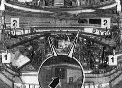
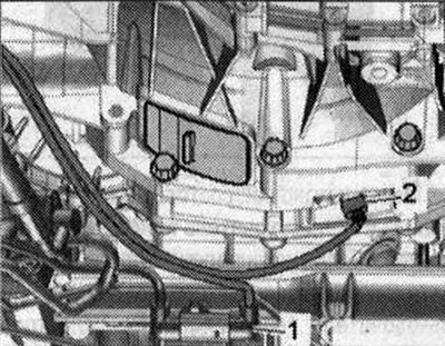
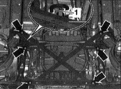
Remove noise insulation screens "1" and "2". Remove the left additional muffler.
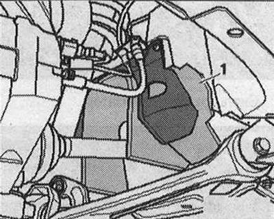
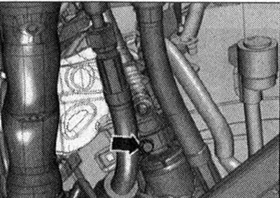
Unscrew nut "1" of the hydraulic line of the power steering. Risk of damage to chassis parts. If the support of the power unit, steering gear or the spacer crosspiece of the subframe is incorrectly installed, the car must not be placed on the wheels. Unscrew the bolts "arrows" and remove the spacer crosspiece of the subframe.
Remove the right catalytic converter.
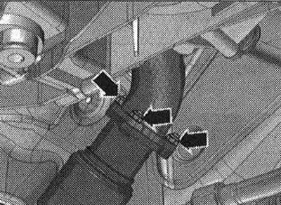
Unscrew the "arrow" bolts of the ATF lines.
Remove the stretcher. Remove the end wall of the radiator tank.
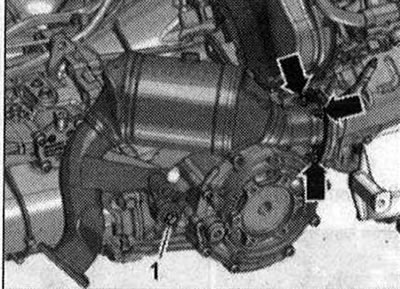
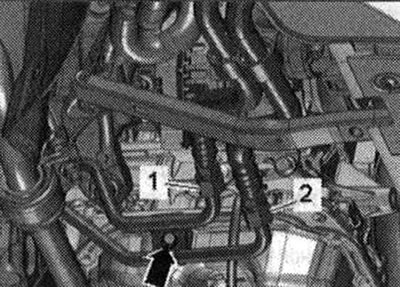
To collect the leaking ATF, place a rag under the disconnection point. Unscrew bolts "1" and "2", remove the ATF lines from the gearbox and tie them up from above. Close the open lines and pipes with clean plugs from the plug set for the "VAS 6122" engine.
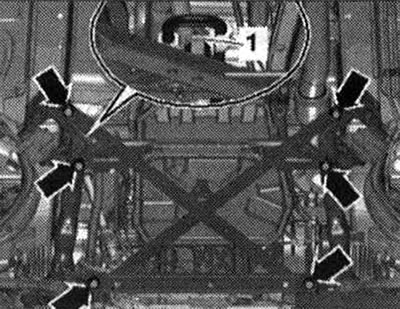
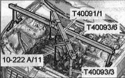
Unscrew the bolts "2...5" of the gearbox and engine connection accessible from above. Install the crossmember "10 - 222 A" with the connector "T40091/3" on the shock absorber strut cups on the left and right, as shown in the figure. Fasten the lead screw "10 - 222 A/11" on the right engine suspension eye.
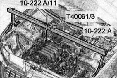
Install other parts of the crossmember "10222 A" as shown in the figure. To do this, install the support "T40093/3" on the fold of the side member sheet. Fasten the lead screw "10222 A/11" on the left front eye of the engine suspension.
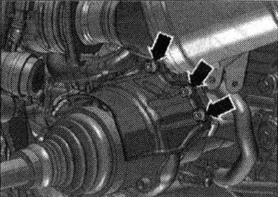
Unscrew the "arrow" bolts and remove the heat-insulating shield of the right drive shaft.
Unscrew the "arrow" bolts and remove the heat-insulating shield of the left drive shaft. Unscrew the left and right drive shafts from the shafts with the gearbox flange.
Caution! Risk of failure of the gearbox control unit (Mechatronik) due to static discharge. Do not touch the contacts in the gearbox plug with your hands.
To remove static charge, touch with your hand (without gloves) to the gearbox housing. Disconnect the gearbox plug connector by turning the rotary clamp counterclockwise "arrow". Release the wiring harness on the gearbox.
Disconnect plug connector "2" of engine speed sensor "G28" and release the electric wire. "Pos. 1" is not taken into account.
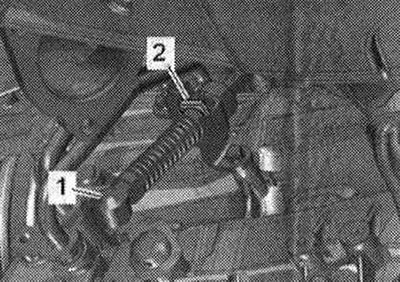
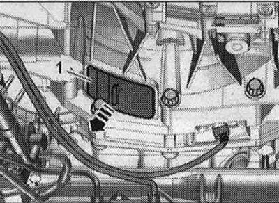
Press the ball joint "1" of the gearbox selector cable with the "80-200" lever from the shift shaft lever. Remove the locking bracket "2" and disconnect the automatic transmission selector cable from the gearbox. The selector cable must not be bent or broken.
Caution! Risk of damage to the airbag coil spring. Only disconnect the universal joint from the steering gear when the front wheels are in the straight-ahead position. Do not change the position of the steering wheel or steering gear any further; if necessary, secure the steering wheel with adhesive tape.
Unscrew the bolt "arrow" of the universal joint. Press the universal joint of the steering gear and move it completely upward.
Unscrew the bolt, press the locking tab away from the gearbox and move the "arrow" back.
If present, unscrew the "arrow" bolts and remove the cardan shaft heat shield.
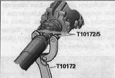
Unscrew the bolt securing the propeller shaft to the gearbox, while holding it from turning with the counter support "T10172" with the help of "T10172/5". Move the propeller shaft towards the rear main gear; constant velocity joints are movable in the axial direction. Tie the cardan shaft to the side.
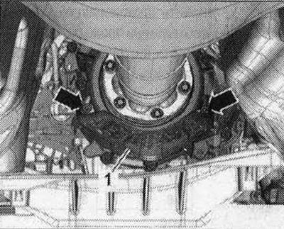
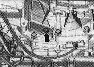
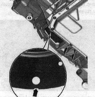
Remove the cover "1" under the "arrow" gearbox.
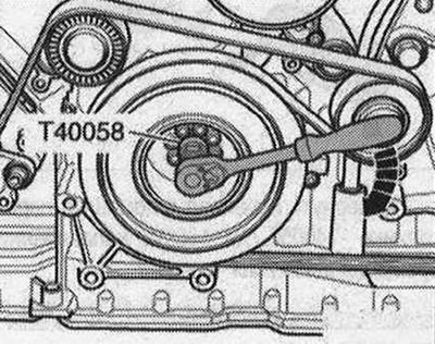
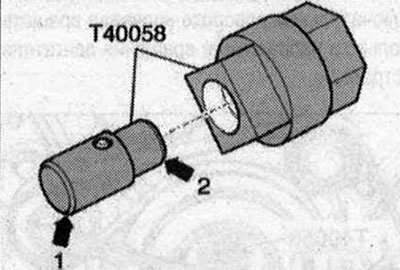
Insert the guide pin of the adapter "T40058" as follows: the large diameter "arrow 1" faces the engine, the small diameter "arrow 2" faces the adapter.
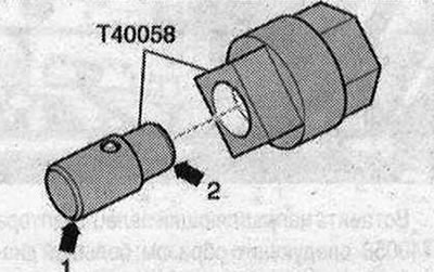
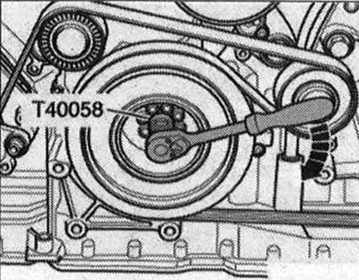
Hold the crankshaft to unscrew the torque converter mounting bolts using the adapter "T40058". During the final turn, rotate the crankshaft only in the direction of engine rotation "arrow".
Unscrew the 6 "arrow" bolts of the torque converter; to do this, turn the crankshaft by 60° in the direction of engine rotation.
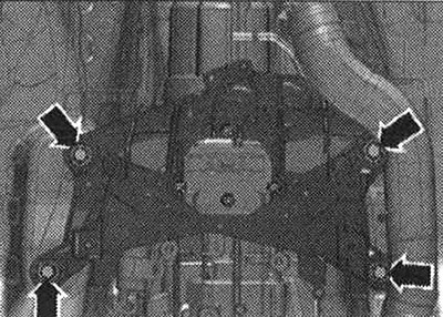
Unscrew bolt "1" of the starter. Remove the starter from the gearbox and leave it in the installation position. Unscrew the remaining bolts "6...11" of the engine/gearbox connection. Install the engine and gearbox lift with the gearbox mount "T40173" under the gearbox and secure with the tension belt "1", as shown in the figure. For clarity of the image, the gearbox mount "T40173" is not shown in the figure. Unscrew the bolts "arrows" of the tunnel crossmember.
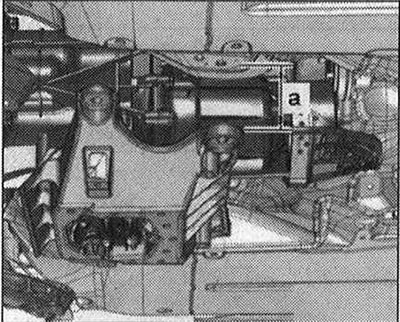
First, lower the gearbox using an engine and gearbox lift by dimension "a". Dimension "a" = maximum 100 mm.
Lightly tighten both lead screws "10 -222 A/11". Press the gearbox away from the engine and carefully lower it using a tilting device.
Installation of the control unit
Note: Replace the bolts that are tightened with additional tightening. Replace the self-locking nuts and bolts, as well as the sealing rings, gaskets and sealing cuffs. Secure all hose connections with hose clamps of the appropriate standard. When installing, reinstall all cable ties in their original locations.
Tightening torques when installing gearboxes
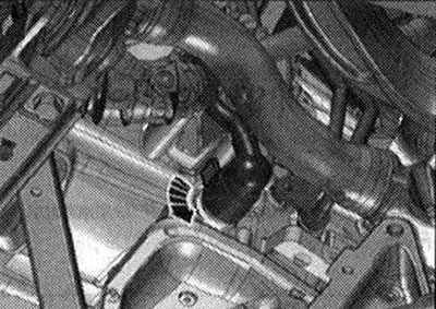
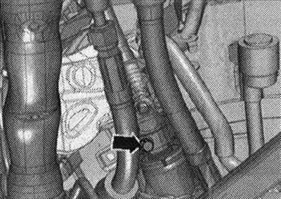
As a rule, before installing a replacement gearbox, blow out the ATF oil lines and ATF oil cooler with compressed air (max 10 bar). Before installation, it is necessary to clean the threaded holes in the cylinder block from any deposits using a tap. When installing a gearbox from the exchange stock: install the gearbox support, gearbox cushion and tunnel crossmember on the new gearbox. Install the gearbox on the gearbox mount "T40173" and secure with tension belt "1", as shown in the figure. Before connecting the engine and gearbox, perform the following preparatory actions: rotate the torque converter so that the hole next to the notch "arrow" is visible in the opening at the bottom of the gearbox housing, as shown in the figure. There is only one notch on the perimeter, so the torque converter should be rotated accordingly.
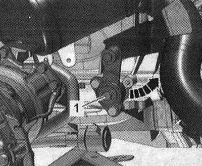
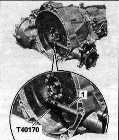
Install the "T40170" transport protection from below under the gearbox housing and attach it to the shaft with flange "1".
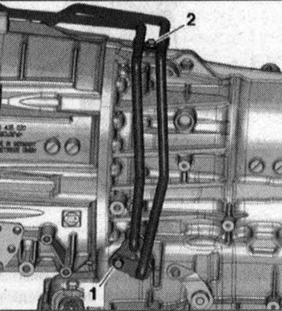
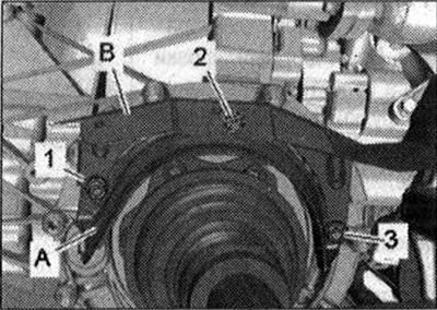
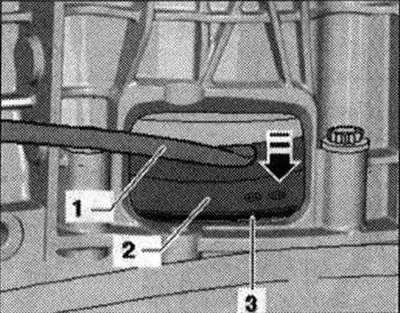
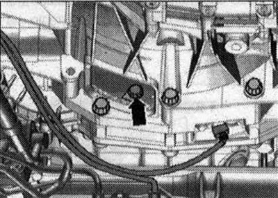
Check the cylinder block for the presence of centering bushings "A" for the engine and gearbox; insert the bushings if necessary. Check the aluminum bolts connecting the engine to the gearbox for reuse and mark them if necessary. Attach the gearbox to the engine and tighten bolts "1, 6...11". Remove the "T40170" transportation protection. Loosen the lead screws "10 - 222 A/11". Raise the gearbox and tighten the "arrow" bolts of the tunnel crossmember. Loosen the harness and remove the lift with the "T40173" gearbox mount from under the gearbox. The next stage of the work is necessary to ensure uniform adhesion of the torque converter to the driven disk without skewing. Slightly press the torque converter "2" using the mounting lever "1" away from the driven disk "3" in the "direction of the arrow".
Tighten the torque converter bolts on the driven disk as follows. Use a 16 mm ring spanner to tighten the bolts "V.A.G 1332/14". Screw in the first bolt "arrow" by hand (2 Nm).
Insert the guide pin of the adapter "T40058" as follows: the large diameter "arrow 1" faces the engine, the small diameter "arrow 2" faces the adapter.
Turn the crankshaft using the adapter "T40058" by 180° in the direction of engine rotation "arrow".
In this position of the crankshaft, tighten the accessible bolt "arrow" to a torque of 60 N·m. Then turn the crankshaft by 60° and tighten the remaining 5 bolts to a torque of 60 N·m. Tighten the remaining bolts "2...5". Install in the reverse order. Screw the cardan joint to the steering gear.
Install the subframe spacer crosspiece. Install the selector cable drive. Install the ATF lines. Bolt the left and right drive shafts to the gearbox flange shafts. Install the drive shaft heat shields.
Install the propeller shaft. Install the exhaust system and align it without tension. Install sound insulation. Consider the measures required after connecting the battery. Check and adjust the selector cable. Check and adjust the ATF oil level.
Tightening torques (Nm)
| Bolts and nuts | |
| M6 | 9 |
| M7 | 15 |
| M8 | 20 |
| M10 | 40 |
| M12 | 65 |
PTO shaft heat shield - tightening torque
Tighten the drive shaft heat shield arrow bolts to 23 Nm.
Fastening the gearbox to the engine
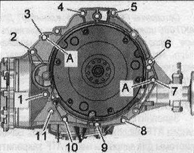
| Pos. | Bolt | Nm |
| 1 | M10x50 (1) | 65 |
| 2.6 | M12X100 (2) | 30 + 90° |
| 7 | M12X125 (2) | 30 + 90° |
| 8,11 | M 10x60 (2) | 15 + 90° |
| 9 | M1 0x75 (2) | 15 + 90° |
| 10 | M1 0x95 (2) | 15 + 90° |
| A | Centering bushings | |
- (1) Strength of bolts 10.9. Steel bolt can be used repeatedly.
- (2) Aluminum bolts can be used twice.
Aluminum bolts "2...11" can be used twice. Therefore, after the first use, mark such bolts with two notches "X" "arrow". In order not to damage the bolts when making the notches, do not clamp them in a vice. Insert the bolt as shown in the figure into the 14 socket head with a 1/2 inch drive, which can then be secured in a vice. Do not reuse bolts marked with "X".
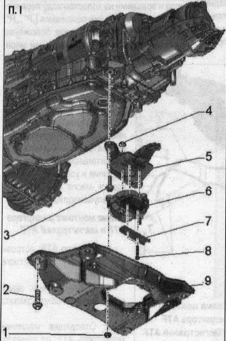
Tunnel crossmember, gearbox cushion and gearbox support I 1. Nut: Remove only if the transmission mount needs to be disconnected from the transmission support; 20 Nm; 2. Bolt: 70 Nm; 3. Bolt: 40 Nm; 4. Nut: 20 Nm; 5. Gearbox support; 6. Gearbox cushion; 7. Lower support of the gearbox cushion; 8. Bolt: Remove only if the transmission mount needs to be disconnected from the transmission support; replace; 20 Nm + 90° turn; 9. Tunnel crossbar
This article was previously published on the resource: audimanual