



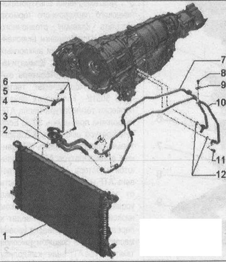
ATF radiator and ATF lines installation diagram 1. ATF radiator: built into the liquid coolant radiator; 2. Sealing ring: replace; lubricate with ATF before inserting; 3. Oil return line A from ATF radiator to gearbox; before dismantling, mark the location of the ATF oil lines, there is a risk of substitution; 4. Sealing ring: replace; lubricate with ATF before inserting; 5. ATF oil supply line: from gearbox to ATF radiator; before dismantling, mark the location of the ATF oil lines, there is a risk of substitution; 6. Bolt: 5 Nm; first, insert the ATF lines with new sealing rings by hand until they stop; 7. ATF oil supply line: from gearbox to ATF radiator; before dismantling, mark the location of the ATF oil lines, there is a risk of substitution; nuts for highways, 29 Nm; aTF lines are connected to each other by means of a counter; 8. Bolt: 8 Nm; 9. Holder; 10. ATF oil return line: from ATF radiator to gearbox; before dismantling, mark the location of the ATF oil lines, there is a risk of substitution; nuts for highways, 29 Nm; aTF lines are connected to each other by means of a counter; 11. Bolt: 20 Nm; first, insert the ATF lines with new sealing rings by hand until they stop; the support bar of the lower ATF line must fit snugly against the gearbox thread; the support bar of the upper ATF line must be in contact with the lower line; 12. O-rings: replace; lubricate with ATF before inserting
This publication is borrowed from the resource: AudiManual.ru