



Table of contents: Replacing the belt pulley ↓ Removal the belt pulley from the air… ↓ Installation ↓
Instructions. At the start of production, compressors of the brand "Denso" of the type "6 SEU14" were installed on cars with 4 "cyl. and 6" cyl. engines. It is possible that later, depending on the engine and time of manufacture, compressors of other manufacturers or other designs will also be installed. The compressor on a car with a 4-cyl. engine and 6-cyl. TDI engine can be removed and installed without opening the refrigerant lines. For cars with a 6-cylinder gasoline engine, the climate control compressor of the unit can be removed from the bracket only with the air conditioning circuit open.
Replacing the belt pulley
Instructions. If the pulley overload protection has been triggered, check the compressor for ease of movement before replacing it. If the air conditioner compressor moves with difficulty, replace it as an assembly. To remove the belt pulley, you do not need to remove the compressor from the engine. Depending on the engine version, you may need to remove the panel from the car and move it forward a little (to free up some space). Depending on the compressor type and engine model, different pulley models may be installed (different diameters). As a spare part, the belt pulley with the driven disk and cap has an individual number. The belt pulley and the driven disk are fastened with a bolt (the bolt is not needed and is disposed of). During manufacturing, a prescribed amount of a certain lubricant is introduced into the thread of the driven disk through this bolt; this volume of lubricant is sufficient for a single installation of the driven disk on the compressor shaft (therefore, the removed slave disk cannot be reused).
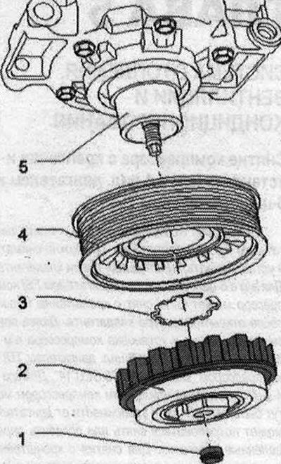 1. Cap; 2. Drive disk. Replace. Secure to the air conditioning compressor drive shaft, clean the compressor shaft threads before installing the driven disk. The threads of the new driven disk are already lubricated with the prescribed amount of a certain lubricant during production. Overload protection is triggered when the torque is too high (eg, difficult operation of the compressor), and the pulley rotates freely without transmitting torque to the compressor. Rubber elements for disconnecting the pulley from the compressor drive shaft (vibrations are dampened and noise is suppressed). For installation, lightly lubricate the rubber elements, e.g. with tire paste or soap solution (antifriction agent). Tightening torque 30 Nm; 3. Retaining ring. Replacement. Install correctly (flat side to compressor); 4. Pulley. The pulley is made of plastic and is not impact resistant, so it should be handled with extreme care. Different designs(for example, depending on the engine type); 5. Air conditioning compressor. Depending on the engine model and export versions of the car, different models may be installed. Before installing the pulley, clean the compressor flange. Clean the compressor shaft thread and lightly lubricate it
Removal the belt pulley from the air conditioning compressor and reinstalling it
Instructions. Follow the instructions for replacing the belt pulley "E". Perform the preliminary work in the same way as when removing the belt pulley. The pulley is made of plastic and is not impact-resistant, so handle it with special care. If the overload protection of the driven disk "C" is triggered, the belt pulley "E" can be turned with the outer part of the driven disk "C" without turning the compressor shaft "B" and the hexagon "D" installed on the driven disk (the inner part of the driven disk "C").
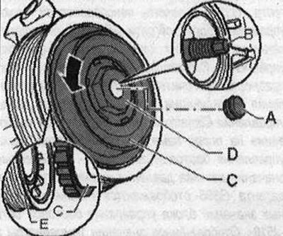
Remove cap "A". Hold compressor drive shaft "B", for example, with a socket Allen key (7 mm key) and turn driven disk "C" with belt pulley "E" in the direction of arrow "arrow".
Instructions. The compressor drive torque is transmitted to the compressor shaft through the bolted connection of the driven disk "C" on the compressor shaft. If, during operation of the air conditioner compressor, the driven disk "C" has screwed onto the compressor shaft so tightly that it cannot be removed (a 7 "B" Allen key may not transmit the required tightening torque), the compressor must be replaced.
Remove driven disk "C". Remove retaining ring "A". Remove belt pulley "B".
Installation
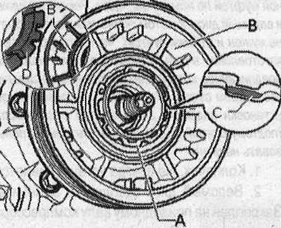
Instructions. Replace the retaining ring "A". Clean the compressor flange before fitting the pulley "B". When fitting the retaining ring "A", make sure that the ring is not bent more than necessary. Fit the belt pulley "B". Insert the retaining ring "A" with the correct side, the side with the bevel "C" facing away from the compressor (the flat side faces the compressor). Clean the compressor shaft threads. The threads of the new driven disk are already lubricated with the prescribed amount of a certain lubricant during production.
To install the driven disk, lightly lubricate the rubber elements "D", for example with tire paste or soap solution (antifriction agent). Insert rubber elements "D" according to the figure into the belt pulley "B". Place the rubber element of the driven disk "C" on the belt pulley "E" so that the driven disk "C" is located at the thread of the compressor shaft "B". Screw the driven disk "C", turning it counterclockwise "arrow", onto the compressor shaft "B". Hold the drive shaft of the compressor "B", for example, with an Allen key (7 key) and turn the driven disk "C" with the belt pulley "E" counterclockwise "arrow" (tightening torque 30 Nm).