



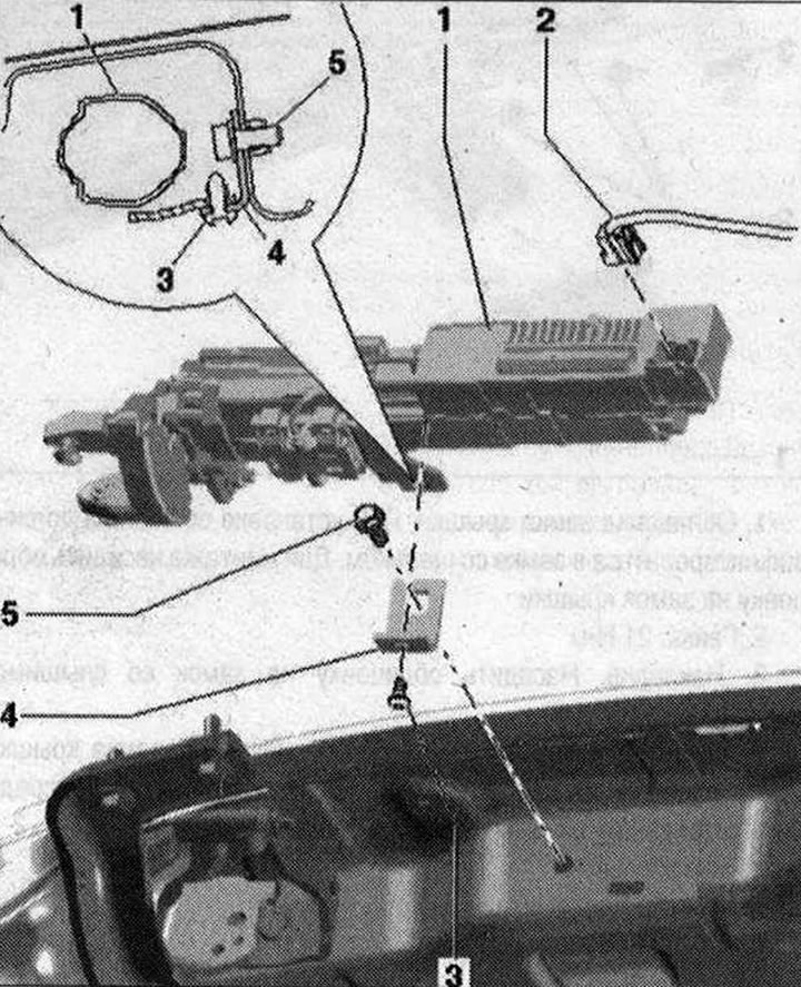
Trunk lid engine parts and components 1. Motor in the tailgate control unit "V375" on the left for the tailgate. The rear roof panel trim has been removed. Detach the trim of the D-pillars in the drive area, carefully press to the side if necessary. Install or remove the drive unit only with the tailgate fully open. Before removing the drive unit, loosen the lock nut on the eccentric bolt. Disconnect plug connection "2". Loosen the lock nut on the drive unit. The eccentric bolt must have a loose fit in the hole in the hinge bracket. If necessary, loosen the eccentric bolt by turning it slightly to the right. Unscrew bolt "3" on holder "4". Unscrew the bolt in the hinge bracket and remove the drive unit "1" in the transverse direction; 2. Electrical connector. Remove before dismantling the drive unit; 3. Bolt 8 Nm; 4. Bracket. The holder is installed in a specific position at the factory using a special device and must not be changed. If the holder also needs to be replaced during repairs after an accident, proceed as follows. The trunk lid must be installed with gas struts. First, lightly secure holder "4" with bolt "5" on the drive unit. The holder must still remain movable. Install the drive unit on the lid hinge parallel to the axis and slide it until the engine bushing stops. The drive unit bushing must fit against the plane of the hinge axis flange. Secure holder "4" to the body with bolt "5" and tighten to a torque of 21 N·m. Tighten bolt "3" to a torque of 8 N·m. Tighten the eccentric bolt with a lock nut on the drive unit to a torque of. When tightening the lock nut, the eccentric bolt is fixed in the hinge motionless. Therefore, when tightening the lock nut, it is not allowed to hold the eccentric bolt by the hexagon with a wrench. When removing the drive unit, this tightening is loosened by briefly turning the eccentric bolt hexagon to the right after loosening the lock nut. Tighten the drive bolt to 11 Nm; 5. Bolt. 21 Nm
Install the motor in the trunk lid control unit "V375" into the hinge
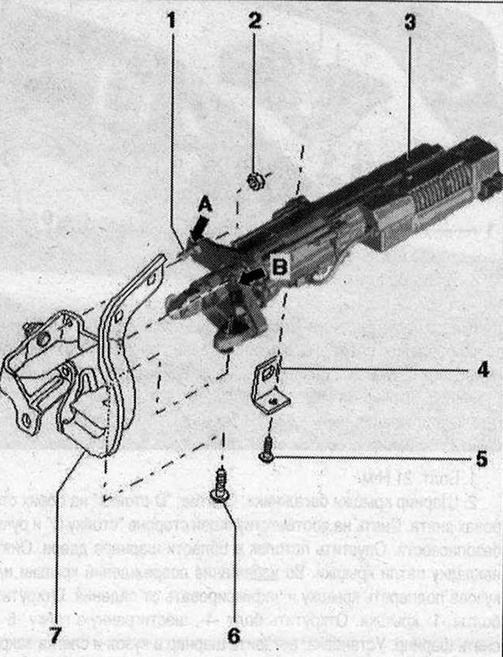 1. Hexagon eccentric bolt. When tightening the lock nut, the eccentric bolt is fixed in the joint. Therefore, when tightening the lock nut, it is not allowed to hold the hexagon of the eccentric bolt with a wrench. When removing the drive unit, this tightening is loosened by briefly turning the hexagon of the eccentric bolt to the right after loosening the lock nut; 2. Locknut. 6 Nm. Self-locking. Before removing the drive unit, it is necessary to loosen the locknut on the eccentric bolt. If necessary, loosen the eccentric bolt in the hinge bracket by turning the Allen key briefly; 3. Lid drive. Insert into the hinge from the side with the bushing "arrow B" and the loose eccentric bolt "arrow A". The bushing of the drive unit must fit against the plane of the flange of the hinge axis. In this case, the sleeve of the drive unit correctly enters the hinge lever "7". Tighten the bolt "5" of the drive unit fastening on the holder "4" with the proper torque. Tighten the lock nut "2" with the proper torque. Tighten the screw "6" with the proper torque; 4. Bracket. The holder is installed in a specific position at the factory using a special device, which is not allowed to be changed. If, during repairs after an accident, it is necessary to replace the holder, proceed as follows:; 5. Bolt 8 Nm; 6. Bolt. 11 Nm. Self-tapping, must be replaced after removal; 7. Hood hinge