
Table of contents: Brake fluid specification FMVSS 116… ↓ Checking the front brake pads ↓ Checking the rear brake pads ↓ Checking brake hoses ↓ Replacing brake fluid ↓ Safety instructions for vehicles… ↓
Brake fluid specification FMVSS 116 DOT 4
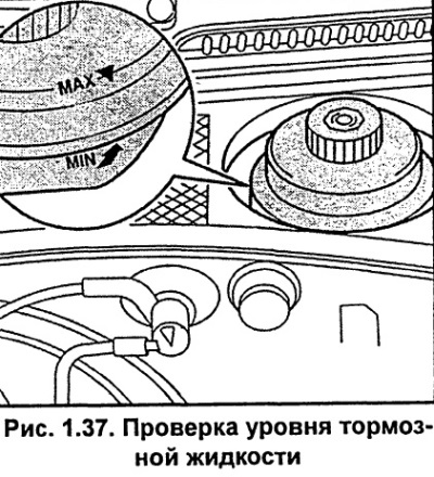
The brake fluid reservoir is located on the left side of the engine compartment. The reservoir cap has a vent hole that should not be blocked.
The tank has a transparent body and the brake fluid level can be monitored from the outside. A brake system control lamp signals that the brake fluid level in the tank is too low.
The brake fluid level should always be between the MAX and MIN marks (see fig. 1.37).
When necessary, add only fresh brake fluid meeting FMVSS 116 DOT 4 specification.
A slight drop in the brake fluid level occurs during vehicle operation due to wear of the brake linings and automatic adjustment of the brake shoes. This is a completely normal phenomenon.
If the brake fluid level has dropped significantly in a short period of time or has dropped below the MIN mark, the cause may be a leak in the brake system. The brake system warning light signals that the brake fluid level in the reservoir is too low.
Brake fluid absorbs moisture. Therefore, during the operation of the car, the brake fluid takes a certain amount of water from the surrounding air. Too much water in the brake fluid can eventually cause corrosion of the working brake system components. In addition, this significantly reduces the boiling point of the brake fluid.
If the brake fluid is very old, it is possible that, under high load on the service brake system, steam bubbles may form in the system. This has a negative effect on the efficiency of the service brake system and, therefore, on traffic safety.
Brake fluid is poisonous. Therefore, it should be stored only in closed original containers and especially out of reach of children. In addition, it should be borne in mind that brake fluid destroys paintwork.
Checking the front brake pads
The thickness of the outer brake pads can be checked through the holes in the wheel rim. The thickness of the inner brake pads can be checked using a flashlight and a mirror.
Attention. It is known that the front brake pads on the front passenger side wear out more intensively, therefore, the brake pads must be checked on the right front wheel.
Use paint or a marker to mark the position of the wheels relative to the hubs. This is necessary to reinstall the wheels in their original position, which maintains their balance. Loosen the front right wheel mounting bolts and tighten the handbrake, then raise the front of the car and secure it on stands. Remove the right front wheel.
Using a caliper, measure the thickness a (Fig. 1.38). of the brake shoe.
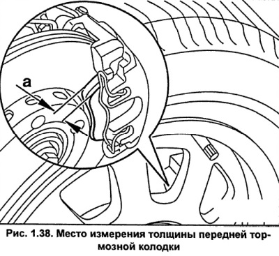
The minimum permissible thickness of the brake pad together with the backing plate is 7 mm. If the brake pad lining is worn down to the minimum thickness, all four brake pads must be replaced as a set.
Install the wheel, aligning the previously applied marks, and secure it with bolts.
Lower the vehicle to the ground and tighten the wheel mounting bolts evenly, in several stages, in a diagonal sequence, to a torque of 120 Nm.
Attention. According to the empirical relationship, with a mileage of 1000 km, the wear of the brake pad is 1 mm.
Checking the rear brake pads
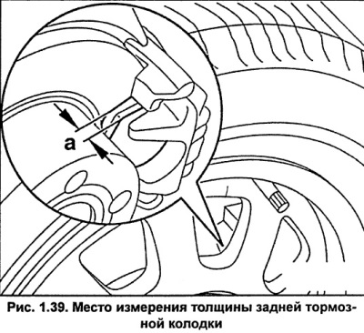
The thickness of the outer brake pads can be checked through the holes in the wheel rim. The thickness of the inner brake pads can be checked using a flashlight and a mirror.
The minimum permissible thickness of the rear brake pad, as well as the front one, together with the carrier plate is 7 mm.
Checking brake hoses
Brake pipes and hoses are used to transfer brake fluid from the master brake cylinder to the wheel brake cylinders.
Brake hoses provide movable connections between the moving and fixed parts of the vehicle.
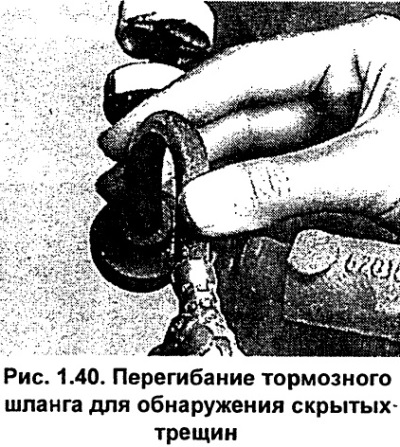
When bending the brake hose, check for hidden cracks, which cannot always be detected by simple inspection (see fig. 1.40).
When installing a new brake pipe or brake hose, make sure it is securely fastened in the brackets and is kept away from moving or hot parts.
Turn the front wheels from lock to lock, making sure that the brake hoses do not touch the front suspension components or the vehicle body.
Brake hoses must not come into contact with oil or fuel. Also, brake hoses must not be coated with varnish or other protective compounds.
Replacing brake fluid
Every two years the brake fluid should be replaced, preferably at the end of the winter season.
When handling brake fluid, please keep the following in mind:
- Brake fluid is poisonous. It should never be sucked out by mouth through a hose. Store brake fluid in containers that prevent accidental use as a food liquid
- Brake fluid is very corrosive, so it should not come into contact with the car's paintwork, otherwise it should be wiped off immediately and the area should be washed with plenty of water.
- Brake fluid is hygroscopic, meaning that it absorbs moisture from the air. Therefore, brake fluid should only be stored in tightly sealed containers.
- Brake fluid that has been used in the brake system cannot be reused. When bleeding the brake system, use only fresh brake fluid.
- Brake fluid should not come into contact with mineral oils. Even a small amount of mineral oil makes the brake fluid unusable and disables the brake system. Brake system plugs and seals are damaged when in contact with products containing mineral oil. Do not use rags containing mineral oils for cleaning.
If air gets into the hydraulic brake system, it is necessary to bleed it, which is usually done with a special device. However, the brake system can be bled using the brake pedal, for this you will need an assistant.
Safety instructions for vehicles with ABS
If the brake fluid level in the replenishing tank drops to the bottom when bleeding the hydraulic brake system, air is sucked in and enters the ABS hydraulic pump. In this case, bleeding must be done at a service station using special equipment. When installing a new brake hose, bleeding must also be done at a service station.
During bleeding, it is necessary to monitor the level of brake fluid in the replenishment tank.
Bleeding sequence: 1. Right rear caliper; 2. Left rear caliper; 3. Right front caliper; 4. Left front caliper.
Unscrew the cap from the refill tank.
Caution. The bleed nipples must be opened very carefully so as not to break them. It is recommended to apply a rust-corroding agent to the nipples approximately two hours before bleeding. If the bleed nipples turn with difficulty, the brake system must be bled at a service station.
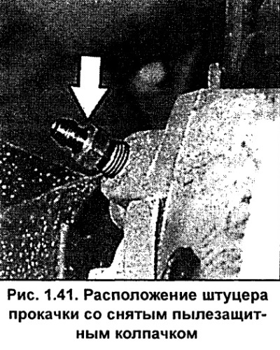
To access the bleed nipple, raise the vehicle on a lift or remove the corresponding wheel (see fig. 1.41). Remove the dust cap from the bleed nipple of the right rear caliper, clean it and put a clean transparent hose on it, the other end of which is lowered into a container partially filled with brake fluid.
Place the gear shift lever in neutral position and start the engine.
The assistant should press the brake pedal 3-5 times with an interval of 2-3 seconds to increase the pressure in the brake system. When pressing, an ever-increasing resistance of the brake pedal should be felt.
Once sufficient pressure has been reached, press the brake pedal all the way down and hold it in this position.
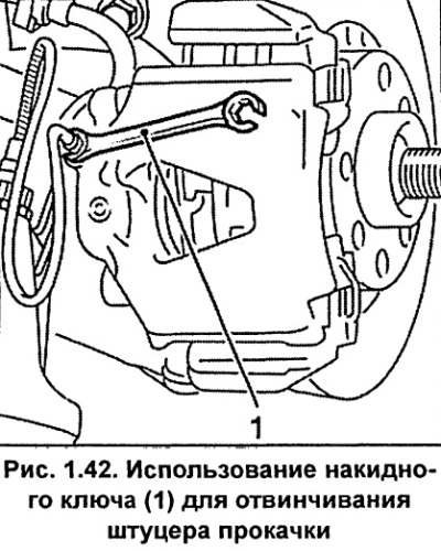
Using an open-end wrench, unscrew the bleed nipple 1 by half a turn (Fig. 1.42).
While continuing to press the pedal, force the fluid in the system together with the air through the hose into the container. At the same time, make sure that the end of the hose is always in the container, below the level of the brake fluid.
Once the pedal reaches the extreme forward position and the fluid stops flowing out through the hose, tighten the bleed nipple until it stops
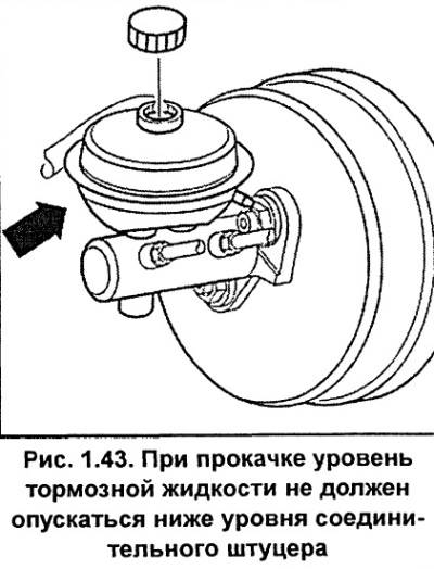
Vehicles with manual transmission: Bleed the right rear wheel until the brake fluid level in the reservoir drops to the level of the connecting nipple (see fig. 1.43). Add fresh brake fluid to the reservoir.
To replace the brake fluid in the working cylinder, it is necessary to pump out about 100 cm³ of fluid during the bleeding process.
Screw on the bleed screw.
Wipe the bleed nipple clean and install the protective cap.
Add fresh brake fluid to the reservoir up to the MAX mark.
In the same way, pump out the brake fluid from the other brake circuit in the following sequence: rear right, rear left, front right, front left.
The brake fluid flowing out of the bleed nipple must be clean and free of air bubbles.
To replace the brake fluid in one circuit, it is necessary to pump out about 250 cm³ of fluid during the bleeding process.
Press the brake pedal, which, if there is no air in the hydraulic brake system, should travel about ⅓ of its travel.
Screw the cap onto the brake fluid reservoir.
Finally, perform several braking maneuvers on a street with little traffic. When braking hard, the brake pedal should pulse, indicating that the ABS is working.
[The original text of the material can be found on the website: AUDIMANUAL]