
Table of contents: FN3 support ↓ FNR-G60 Support ↓ Support HP2 ↓ Brembo caliper 18 inches ↓ Support C38/C43 ↓
FN3 support
Attention! It is not recommended to overhaul the caliper yourself. It is better to entrust this work to a workshop, delivering the caliper assembly.
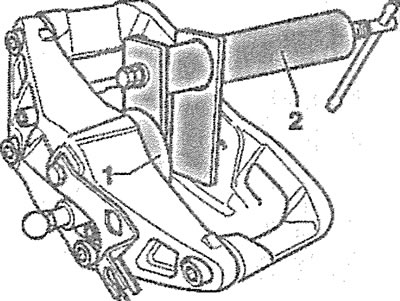
1. Secure the removed caliper in a vice, placing a wooden block on the opposite side of the cylinder to prevent damage to the piston when pushing it out with compressed air, and press the piston together with the cuff out of the cylinder with compressed air (see illustration).
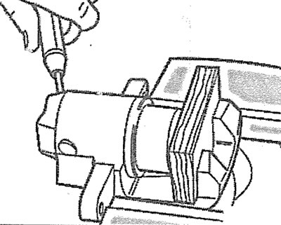
8.1. Secure the removed caliper in a vice and press the piston together with the cuff out of the cylinder with compressed air
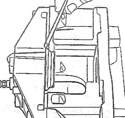
2. Remove the piston sealing ring from the cylinder by prying it up with a plastic wedge (see illustration).
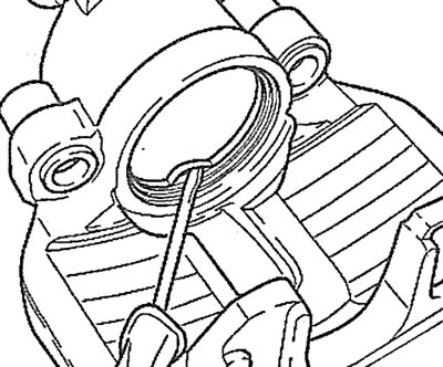
8.2. Remove the piston sealing ring from the cylinder by prying it up with a plastic wedge
3. Inspect the brake caliper. If there is rust or ribbing on the inner wall of the brake cylinder, the caliper must be replaced with a new one.
4. Install the new sealing ring into the groove inside the cylinder bore, lubricating the piston and ring with G052150A2 grease.
5. Place the cuff on the piston (see illustration).
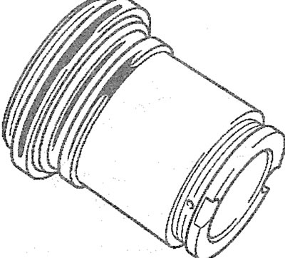
8.5. Place the cuff on the piston
6. Place the piston on the cylinder bore and, being careful not to crush the piston, insert the working edge of the cuff into the groove on the cylinder bore with a plastic wedge (see illustration).
8.6. Insert the working edge of the cuff into the groove on the cylinder bore using a plastic wedge
7. Do not push the inserted piston in completely, because in this case it will not be possible to insert the protrusion on the cuff into the groove on the piston.
8. Press the piston into the cylinder cavity using the appropriate tool (see illustration).
8.8. Press the piston into the cylinder cavity using the appropriate tool
FNR-G60 Support
9. It is not recommended to overhaul the caliper yourself. It is better to entrust this work to a workshop, delivering the caliper as an assembly.
10. Secure the removed caliper in a vice, placing a wooden block on the opposite side of the cylinder to prevent damage to the piston when pushing it out with compressed air, and press the piston out of the cylinder with compressed air (see illustration).
8.10. Secure the removed caliper in a vice and press the piston out of the cylinder with compressed air
11. Remove the piston sealing ring from the cylinder by prying it up with a plastic wedge (see illustration), and a protective cuff.
8.11. Remove the piston sealing ring from the cylinder by prying it up with a plastic wedge
12. Install a new sealing ring into the groove inside the cylinder bore, lubricating the piston and ring with G052150A2 grease (see arrow in illustration).
8.12 Install the new sealing ring into the groove inside the cylinder bore (see arrow)
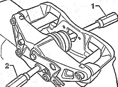
13. Insert the inner end of the cuff into the cylinder bore, then press the cuff into the cylinder using tool 2, placing protective pad 1 on it (see illustration).
8.13. Insert the inner end of the cuff into the cylinder bore, then press the cuff into the cylinder using tool 2, placing protective pad 1 on it
14. Make sure that the cuff is firmly installed in the mounting place and does not come off when tightened by hand (see illustration).
8.14. Make sure that the cuff is securely installed in the mounting location and does not come off when pulled by hand
15. Insert the piston into the cuff hole and push it in slightly with a suitable tool 1 (see illustration).
8.15. Insert the piston into the cuff hole and push it in slightly with a suitable tool 1
Attention! Perform this operation carefully to avoid piston distortion and damage to the cuff.
16. Supply compressed air through the hole under the bleed nipple 2 (max 3 bar), holding the piston so that the air pressure causes the cuff to move onto the piston (see illustration 8.15).
17. Push the piston into the cylinder bore by hand. The outer collar of the cuff will enter the groove on the piston.
Support HP2
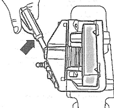
18. Unscrew the bleed nipple from the dismantled caliper and supply compressed air through the hole under the nipple to press out the cylinder pistons.
Attention! The pistons are pressed out one by one. One is blocked by the pressing device "b", and a wooden block "a" is installed opposite the second (see illustration).
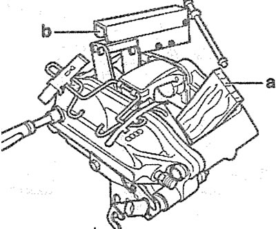
8.18. Press out both pistons one by one, supplying compressed air through the hole under the bleed nipple
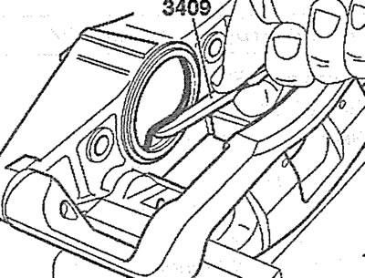
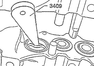
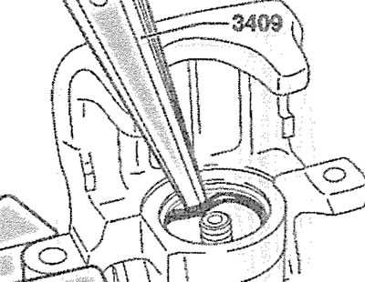
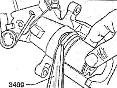
19. Remove the piston sealing rings from the cylinders by prying them with a plastic wedge, for example, AUDI 3409 (see illustration).
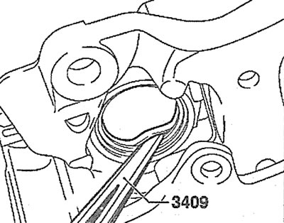
8.19. Remove the piston sealing rings from the cylinders by prying them off with a plastic wedge
20. Before assembly, lubricate the pistons and sealing rings with a thin layer of G052150A2 grease, having cleaned them with alcohol beforehand.
21. Install the sealing rings in their places in the cylinders.
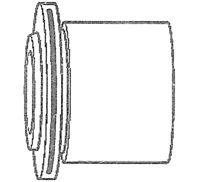
22. Place the sealing cuff on the piston (see illustration).
8.22. Place the sealing cuff on the piston
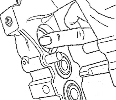
23. Tuck the inner ring of the piston cuff into the cylinder cavity using a plastic wedge, holding the piston near the cylinder bore (see illustration).
8.23. Tuck the inner belt of the piston cuff into the cylinder cavity using a plastic wedge
24. Push the piston into the cylinder cavity by hand and then with a pressing tool. In this case, the outer belt of the cuff will enter the groove on the piston.
Brembo caliper 18 inches
25. Unscrew the bleed nipple from the dismantled caliper and supply compressed air through the hole under the nipple to press out the cylinder pistons.
Attention! The pistons are pressed out one by one. The piston opposite the one being pressed out is blocked by the pressing device "a", and the others - by wooden blocks "b". A wooden plate should be placed in front of the pressing device so as not to damage the piston being extracted (see illustration).
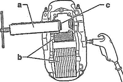
8.25. Press out all the pistons one by one by supplying compressed air through the hole under the bleed nipple
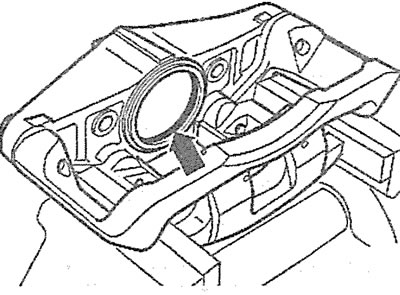
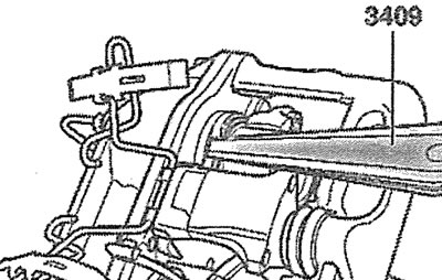
26. Remove the piston sealing rings from the cylinders by prying them with a plastic wedge, for example, AUDI 3409 (see illustration).
8.26. Remove the piston sealing rings from the cylinders by prying them off with a plastic wedge
27. Before assembly, lubricate the pistons and sealing rings with a thin layer of G052150A2 grease, having cleaned them with alcohol beforehand (see illustration).
8.27. Lubricate the pistons and sealing rings with a thin layer of grease before assembly
28. Install the sealing rings in their places in the cylinders.
29. Put the cuffs on the pistons (see illustration).
8.29. Put the cuffs on the pistons
30. Press the piston into the cylinder with your fingers until the piston seal fits into the cylinder groove (see illustration). If necessary, press the piston with a pressing tool.
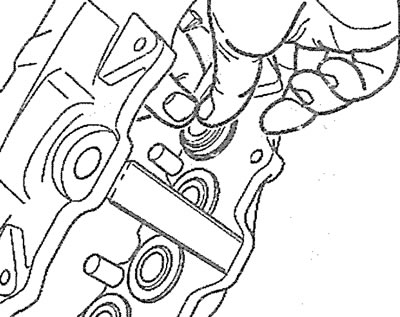
8.30. Press the piston into the cylinder with your fingers until the piston seal fits into the cylinder groove
Support C38/C43
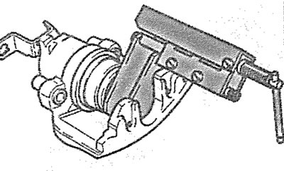
31. Unscrew the piston from the cylinder using the pressing tool B, turning it to the left, and the handle A to the right (see illustration).
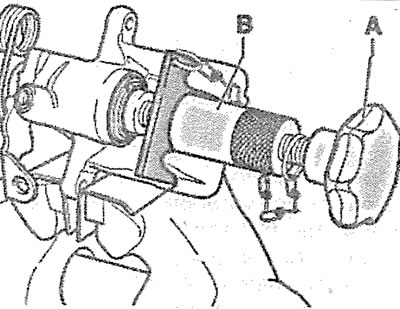
8.31. Unscrew the piston from the cylinder using pressing tool B, turning it to the left, and handle A to the right
32. Remove the piston sealing ring by prying it off with a plastic wedge (see illustration).
8.32. Remove the piston sealing ring by prying it with a plastic wedge
33. Before assembly, lubricate the piston and sealing ring with a thin layer of G052150A2 grease, having cleaned them with alcohol beforehand.
34. Install the sealing ring in its place in the cylinder.
35. Place the sealing cuff on the piston (see illustration).
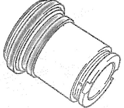
8.35. Place the sealing cuff on the piston
36. Tuck the inner ring of the piston cuff into the cylinder cavity using a plastic wedge, holding the piston near the cylinder bore (see illustration).
8.36. Tuck the inner belt of the piston cuff into the cylinder cavity using a plastic wedge
37. Screw the piston into the cylinder using pressing tool B, turning it to the right and handle A to the left.
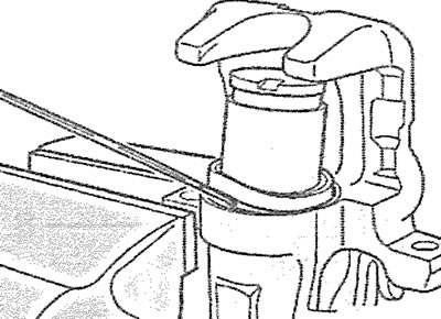
38. Fill the wheel cylinder with brake fluid to remove air. Fill the fluid through the bleed nipple until the fluid comes out through the hole in the brake pipe without air bubbles (see illustration).
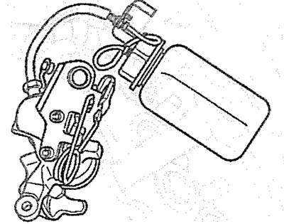
8.38 Fill the wheel cylinder with brake fluid to remove air from it
[The full version is posted on the resource: AudiManual]