
Table of contents: 1 – coolant temperature ↓ 2 – tachometer ↓ 3 – outside air temperature ↓ 4 – speedometer ↓ 5 – Trip meter reset button ↓ 6 – fuel level indicator in the tank ↓ 8 - hands watch ↓ 9 – engine oil temperature ↓ 10 – voltmeter ↓ 11 – instrument lighting ↓
1 – coolant temperature
The indicator works when the ignition is on. However, after switching on, some time must pass before the arrow is set to the position corresponding to the actual temperature.
Cold Engine Temperature Range
While the needle is on the left side of the scale, avoid high engine speeds and loads!
Operating temperature range
During normal driving, the temperature gauge needle should fluctuate within the middle part of the scale.
Under significant engine load and high outside temperatures, the needle may move further to the right on the scale. This should not be a cause for alarm as long as the cooling system warning light does not flash.
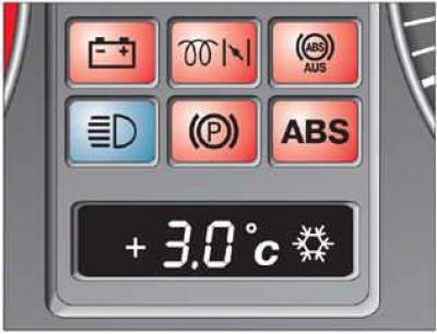
Signal lamp
Flashing coolant temperature/level indicator light while driving indicates low coolant level or overheating. Stop, turn off the engine and determine the cause of the problem.
2 – tachometer
The red sector of the scale corresponds to the range of maximum revolutions, permissible for a short-term running-in and warmed-up engine. It is recommended, however, to switch to a higher gear or reduce the gas at the latest when the arrow reaches this sector of the scale. High-speed modes should be avoided during the running-in period.
3 – outside air temperature
The indicator works when the ignition is on.
When the display of vehicles with automatic air conditioning is switched to Fahrenheit (°F), the outside air temperature gauge automatically changes accordingly.
At temperatures from +5°C to 0°C, a snowflake symbol appears on the display to the right of the main readings.
At temperatures between 0°C and –5°C, a snowflake appears to the left of the main display.
The appearance of the snowflake symbol warns the driver of the need to exercise special caution due to the danger of icy conditions.
When the vehicle is stationary or driving at very low speeds, the temperature indication may be slightly higher than the actual temperature due to the heat radiated by the engine.
4 – speedometer
The division of the speedometer scale into sectors is determined by the engine type. Therefore, discrepancies with the illustration are possible. The speedometer is equipped with a digital counter of the total and single mileage, as well as an indicator of the maintenance interval.
Odometers
The upper counter registers the total mileage, and the lower one – the single mileage. The accuracy of the lower counter's single mileage count is 100 m.
The trip meter is reset to zero by pressing the reset button located next to the speedometer for at least 2 seconds.
Maintenance interval indicator
After the ignition is switched on, the next maintenance indicator flashes for a few seconds in place of the trip meter. When the next maintenance is due, the indicator flashes for about 60 seconds after the engine is started. If desired, without waiting for the full expiration of the indicator time, by pressing the reset button (next to the speedometer) you can switch to a one-time mileage counter.
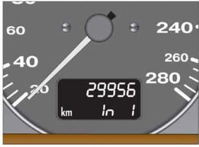
The next maintenance indication appears in advance – 1000 km or 10 days. The following indication may appear:
OEL – maintenance – oil change
ln 1 - inspection service
ln 2 - additional technical maintenance
After the service, the display is returned to its original position at the Audi workshop.
Malfunction indication
If there is a fault in the instrument cluster, the display "dEF" appears instead of the trip odometer reading. Have the fault repaired immediately by an Audi dealer.
5 – Trip meter reset button
The trip meter is reset to zero by pressing the reset button located next to the speedometer for at least 2 seconds.
6 – fuel level indicator in the tank
After turning on the ignition and after refueling, 2 minutes must pass before the arrow is set to the position corresponding to the actual remaining fuel.
The fuel tank capacity of front-wheel drive vehicles is approximately 80 liters, and all-wheel drive vehicles approximately 75 liters. These are approximate values. The actual amount filled may differ slightly from these values.
If the arrow reaches the reserve field, this means that there are about 12 liters left in reserve.
The petrol pump symbol in the instrument cluster also reminds you to refuel. Never run the tank dry.
8 - hands watch
The time is set by the instrument backlight brightness control button. Each time the button is pulled out and turned, the arrow jumps by one minute. If you hold the button in the pulled out position and turn it, the arrows will start to run slowly and then faster and faster along the scale.
9 – engine oil temperature
Until the oil has warmed up, do not attempt to use the engine's full power. If, as an exception, the instrument needle enters the high-temperature range, reduce engine speed. After this, the needle should return to the normal operating range. If the needle remains in the high-temperature range, stop, turn off the engine and check the oil level. If the level is normal and the oil pressure warning light does not flash after starting the engine, you can, avoiding high speeds, drive to the nearest Audi dealership.
10 – voltmeter
The voltmeter shows the voltage of the electrical on-board network. Normal value: 12–14 volts. If the voltage drops below 12 volts with the engine running, check the power supply (battery and generator) at the Audi plant. During engine start-up, the voltage may drop below 8 volts.
11 – instrument lighting
When the lighting is on, the brightness of the instrument lighting can be adjusted by turning the button.