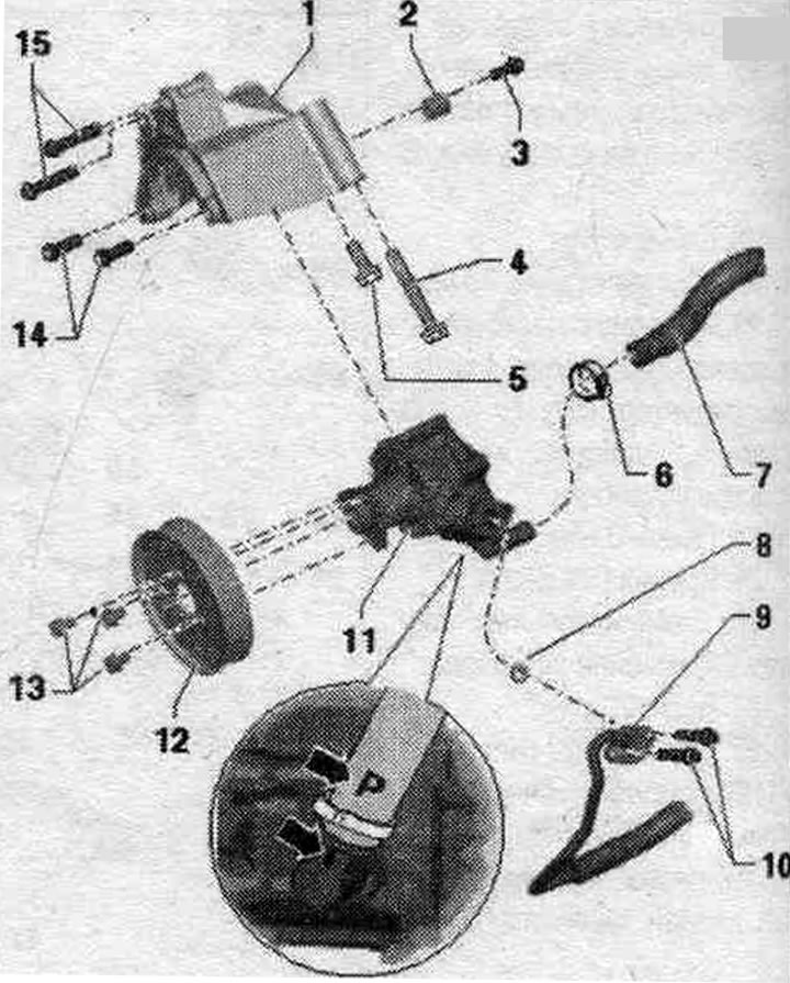
Repair Chevrolet Repair Toyota Repair Honda Repair AvtoVAZ Repair Mercedes-Benz Repair BMW Repair Opel
Home  |  Contacts  |  Sitemap  |    
English Русский
Български
Беларускі
Український
Српски
Hrvatski
Română
Polski
Slovenský
Magyar
AudiManual.ru


  • AUDI 80
  • AUDI 100
  • AUDI A3
  • AUDI A4
  • AUDI A6
  • AUDI A8
  • AUDI Q
  • OTHER
  • ARTICLES
B8 (2007-2015) B7 (2004-2008) B6 (2000-2006) B6 (2000-2006, petrol) B5 (1994-2001) B5 (1994-2001, petrol)

Removal and installation a vane pump, vehicles with a 6-cylinder TFSI engine, vehicles without a dynamic steering system (Audi A4 B8)

  • Home
  • Audi A4
  • B8 (2007-2015)
  • Chassis
  • Steering system
  • Removal and installation a vane pump, vehicles with a 6-cylinder TFSI engine, vehicles without a dynamic steering system
            0
Removing and installing a vane pump, vehicles with 6-cyl. TFSI engine, vehicles without syst. dynamic steering

1. Holder.

1. Holder.
2. Sleeve: To install the vane pump, the sleeve needs to be moved back slightly.
3. Bolt: 20 Nm.
4/5. Bolt: 20 Nm; bracket mounts on the engine; take into account the different lengths of the bolts.
6. Clamp: tighten with clamp pliers; replace when removed.
7. Suction hose: The "P" "arrow" marking on the suction hose must be aligned with the "arrow" profile seam on the vane pump.
8. Sealing ring: replace when removed.
9. Pressure main. Insert the pressure line completely during installation.
10. Bolt: 9 Nm.
11. Vane pump: fill with hydraulic fluid before installation. with oil; bleed the steering wheel; check the slave level. liquids in hydr. syst.
12. Pulley.
13. Bolt: 22 Nm.
14. Bolt: 20 Nm; mounting the vane pump on the bracket.
15. Bolt: 20 Nm; mounting the bracket on the engine.


Repair work for the vane pump is not provided. If there is a fault, the vane pump should be replaced. The vane pump is supplied unfilled. Therefore, before installation, be sure to fill the hydraulic pump with liquid and turn it by hand. Otherwise, noise may occur during operation or damage to the vane pump may occur.


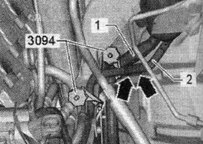
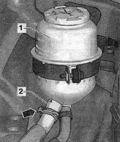
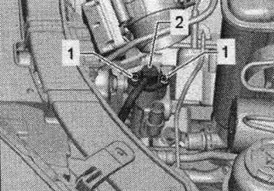
Place the car on a lift. Remove engine cover "1" upwards. Pump out the hydraulic fluid from the reservoir using a device for collecting and pumping out oil. Clamp the suction hose "1" and return hose "2" with hose clamps "3094". Do not attach hose clamps "3094" for hoses with a diameter of up to 25 mm to the return hose "2" near the check valve. Otherwise, the check valve may be damaged. The non-return valve is located in the return hose "2" between the clamps, "arrows". Remove the noise insulation. Drain the coolant.

Place the car on a lift. Remove engine cover «1» upwards. Pump out the hydraulic fluid from the…


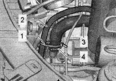
Disconnect coolant lines "1" and "2" from the expansion tank. coolant reservoir. Unscrew the "arrow" nuts and remove the expansion joint. coolant reservoir "3" upwards from the fasteners. Unlock from below on the extension. coolant reservoir plug connector "3" and disconnect. Postpone expansion. coolant reservoir "3" to the side.

Disconnect coolant lines «1» and «2» from the expansion tank. coolant reservoir. Unscrew the…


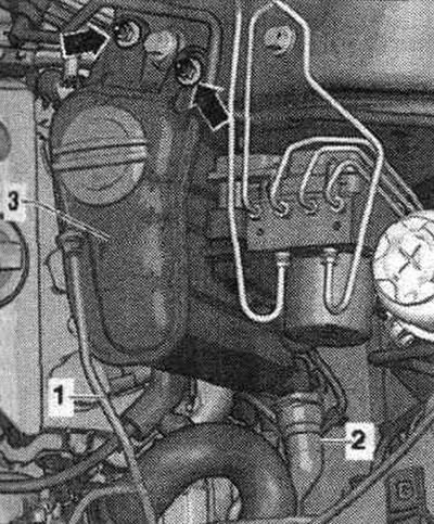
Disconnect coolant hoses "1" and "2" from the coolant pipe and turn them to the side. Disconnect coolant line "3" from the coolant radiator and turn it to the side.


Disconnect coolant hoses «1» and «2» from the coolant pipe and turn them to the side. Disconnect…


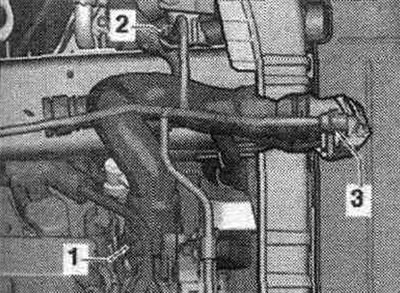
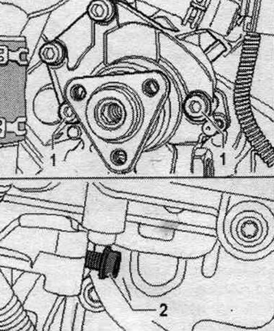
Remove bolt "1" of the upper coolant pipes. Ignore the "arrow".

Remove bolt «1» of the upper coolant pipes. Ignore the «arrow».


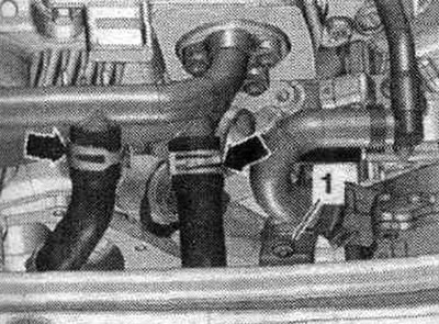
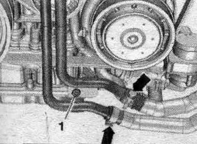
Remove bolt "1" of the lower coolant pipes. Ignore the "arrow".

Remove bolt «1» of the lower coolant pipes. Ignore the «arrow».


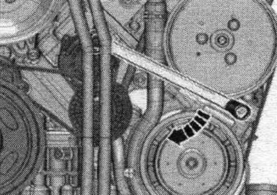
Loosen the poly V-belt and remove it from the vane pump pulley. Rotate the tensioner to loosen the poly V-belt tensioner in the direction of the arrow. Remove the poly V-belt from the vane pump pulley only. Loosen the clamp and remove the tool.


Loosen the poly V-belt and remove it from the vane pump pulley. Rotate the tensioner to loosen the…


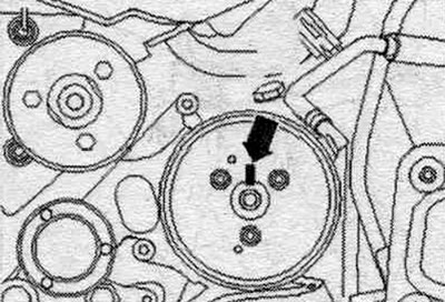
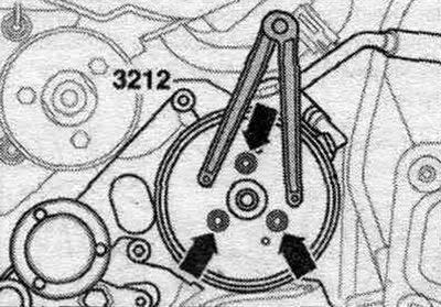
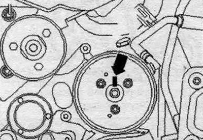
Mark the position of the pulley in relation to the hub. To do this, mark the "arrow." When replacing a vane pump, transfer the marking on the hub from the old pump to the new one. It is impossible to determine the position of the pulley holes relative to the holes in the hub during installation due to limited space.

Mark the position of the pulley in relation to the hub. To do this, mark the «arrow.» When…


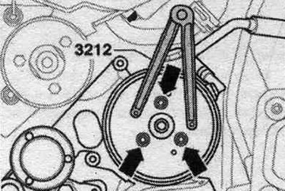
Remove the "arrow" bolts. Use a 3212 2-hole wrench to hold them in place. Remove the vane pump belt pulley. Place a tray under the vane pump.

Remove the «arrow» bolts. Use a 3212 2-hole wrench to hold them in place. Remove the vane pump belt…


If present, carefully cut the cable retainer "1" of the wiring harness "2".


If present, carefully cut the cable retainer «1» of the wiring harness «2».


Unscrew bolts "1" and remove pressure line "2" from the vane pump. Close the vane pump and line connections with clean plugs.

Unscrew bolts «1» and remove pressure line «2» from the vane pump. Close the vane pump and line…


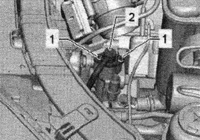
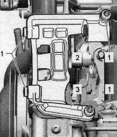
Unscrew the vane pump fasteners from the bracket. To do this, unscrew bolts "1" in the front and bolts "2" in the rear. Bolt "2" is not visible in the bracket; it is shown in the figure in the unscrewed position.

Unscrew the vane pump fasteners from the bracket. To do this, unscrew bolts «1» in the front and…


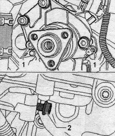
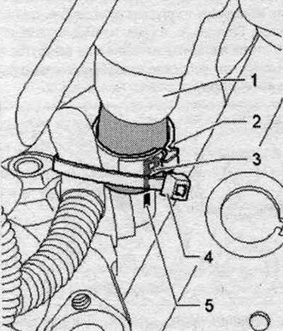
Unlock the spring band clamp "arrow" on suction hose "2" on tank "1" and remove suction hose "2" from the tank. Remove the vane pump with the suction hose from the bracket.


Unlock the spring band clamp «arrow» on suction hose «2» on tank «1» and remove suction hose «2»…


Installation


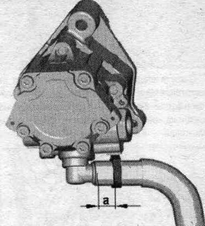
Installation in reverse order. Replace seals and gaskets. rings. Before installing a new vane pump, fill the suction side with hydraulic oil and rotate it by hand until the oil comes out on the discharge side. Secure all hose connections with new clamps. It is not possible to tighten the clamp with hose clamp pliers while the vane pump is installed, so this step must be performed with the pump removed. Before installing the vane pump, attach the suction hose and place it opposite the "P" marking on the molding seam of the vane pump. Secure the suction hose with a new clamp. Pay attention to the installation size of the clamp. The size "a" should be 4 mm.

Installation in reverse order. Replace seals and gaskets. rings. Before installing a new vane pump,…


Insert the vane pump with the suction hose into bracket "3". Sleeve "2" is slightly pushed back.


Insert the vane pump with the suction hose into bracket «3». Sleeve «2» is slightly pushed back.


First, tighten the front bolts "1". Then tighten the rear ones. bolt "2". Tighten bolts "1" and "2".

First, tighten the front bolts «1». Then tighten the rear ones. bolt «2». Tighten bolts «1» and «2».


Press the pressure line "2" into the vane pump until it stops. Then tighten bolts "1".

Press the pressure line «2» into the vane pump until it stops. Then tighten bolts «1».


If installed, secure the wiring harness with a new cable tie "4" to the fitting.

If installed, secure the wiring harness with a new cable tie «4» to the fitting.


Place hose "2" in the engine compartment without tension or kinks and secure it to the tank. Make sure that the hose is not bent or twisted. Clean oily areas in the motorcycle. compartment. Align the "arrow" marking on the belt pulley with the marking on the hub.


Place hose «2» in the engine compartment without tension or kinks and secure it to the tank. Make…


Tighten the belt pulley arrow bolts. Install the poly V-belt of the vane pump. Check the slave level. fluid in the hydraulic system. Remove air from the steering wheel. Check the steering wheel for leaks. Install soundproofing.

Tighten the belt pulley arrow bolts. Install the poly V-belt of the vane pump. Check the slave…


Install the poly V-belt and check the alignment of the poly V-belt. When installing a poly V-belt, ensure that it is correctly seated in the pulleys.
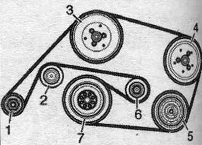
1. Generator.

1. Generator.
2. Guide roller.
3. Coolant pump.
4. Vane pump.
5. Air conditioning compressor. installations.
6. Tension roller.
7. Crankshaft.
The article was checked by auto expert Timur Bazhenov
This article is available at russian, bulgarian, belarusian, ukrainian, serbian, croatian, romanian, polish, slovak, hungarian

Share information:
Previous articles
Audi A4 B8: Steering system
Next articles

Vane pump — vehicles with a 6-cylinder TFSI engine, vehicles…
Vane pump — vehicles with a 6-cylinder FSI engine, vehicles…
Vane pump — vehicles with a 6-cylinder FSI engine, vehicles with…
Removal and installation the hydraulic fluid cooler, vehicles…
Mounting position of hose lines on the reservoir, hydraulic…


Similar articles on other Audi car models:
Power steering pump — removal, overhaul and installation Audi 80 B3 (1986-1991, petrol)
Power steering pump drive belt — removal, installation and… Audi 100 C3 (1982-1990, diesel)
Removal and installation the power steering pump Audi A3 Type 8L (1996-2003)
Removal and installation the cylinder head (diesel engine… Audi A6 C5 (1997-2004)
Removal and installation the engine Audi A8 D2 (1994-2002)
Vane pump, hydraulic lines, expansion tank, vehicles with… Audi Q5 Type 8R (2008-2017)
Removal and installation the cooling system pump Audi A2 (1999-2005)
Link to this page in different formats


Visitor comments

No comments yet


How much will 44 + 27 =


A4(B8, 2007-2015) 
  • General information
  • Operating instructions
  • Power unit
  • Petrol engines 1.8 l
  • Petrol engines 1.8/2.0 l
  • Petrol engines 3.0 l
  • Petrol engines 3.2 l
  • Fuel system (petrol)
  • Diesel engines 2.0 l (CA*)
  • Diesel engines 2.0 l (CJCB)
  • Diesel engines 2.7/3.0 l
  • Diesel engines 3.0 l
  • Fuel system (diesel)
  • Transmission
  • Manual gearbox 0B1
  • Manual gearbox 0B2
  • Manual gearbox 0B3
  • Manual gearbox 0B4
  • Automatic transmission 0B5
  • Automatic transmission 0B6
  • Automatic transmission 0AW
  • All-wheel drive system
  • Chassis
  • Front suspension
  • Rear suspension
  • Brake system
  • Steering system
  • Body
  • Exterior
  • Interior
  • Seats
  • Doors, locks and windows
  • Security system
  • Heating and air conditioning
  • Electrical equipment
  • Audio system
  • Power devices
  • Equipment and devices
  • Lighting and lamps
  • Electrical circuits
 
A4(B7, 2004-2008) 
  • General information
  • Introduction to manual
  • Troubleshooting
  • Operating instructions
  • Maintenance
  • Power unit
  • Petrol engines 2.0 (ALT)
  • Petrol engines 2.0 (TFSI)
  • Petrol engines 1.8 (MPI)
  • Diesel engines
  • Cooling system
  • Air conditioner
  • Fuel and exhaust system
  • Ignition system
  • Starting and charging
  • Transmission
  • Clutch
  • Manual gearbox
  • Automatic gearbox
  • Drive shafts
  • Chassis
  • Brake system
  • Front suspension
  • Rear suspension
  • Steering
  • Body
  • Exterior
  • Interior
  • Electrical equipment
  • Equipment and devices
  • Lighting and signaling
  • Windscreen wipers and washers
  • Electrical diagrams
  • Electrical diagrams (since 2007)
 
A4(B6, 2000-2006) 
  • General information
  • Vehicle Description
  • User manual
  • Maintenance
  • Power unit
  • Gasoline engine
  • Diesel engine
  • Lubrication system
  • Cooling system
  • Supply system
  • Injection system
  • Exhaust system
  • Ignition and control
  • Transmission
  • Gear box
  • Clutch and drive shafts
  • Chassis
  • Brake system
  • Car suspension
  • Steering
  • Body
  • Heating and ventilation
  • Exterior (external elements)
  • Interior (internal elements)
  • Electrical equipment
  • Power devices
  • Lighting and appliances
  • Electrical circuits
 
A4(B6, 2000-2006, petrol) 
  • General information
  • Introduction to the guide
  • Car care
  • Power unit
  • Engine repair
  • Lubrication system
  • Cooling system
  • Injection and control system
  • Ignition system
  • Power and exhaust system
  • Transmission
  • Clutch and drive shafts
  • Car gearbox
  • Chassis
  • Suspension and wheels
  • Steering
  • Brake system
  • Body
  • Interior
  • Exterior
  • Electrical equipment
  • Equipment and devices
  • Lighting and signaling
  • Power devices
  • Electrical circuits
 
A4(B5, 1994-2001) 
  • General information
  • Introduction to the guide
  • Car care
  • Maintenance (gasoline)
  • Maintenance (diesel)
  • Power unit
  • Gasoline engines
  • Diesel engines
  • Engine overhaul
  • Cooling system
  • Fuel injection (gasoline)
  • Fuel system (diesel)
  • Exhaust system
  • Ignition system
  • Transmission
  • Clutch
  • Mechanical gearbox
  • Automatic gearbox
  • Drive shafts
  • Chassis
  • Brake system
  • Car suspension
  • Steering
  • Body
  • Exterior
  • Interior
  • Doors, locks and windows
  • Heating and ventilation
  • Electrical equipment
  • Power devices
  • Equipment and devices
  • Electrical circuits
 
A4(B5, 1994-2001, petrol) 
  • General information
  • Vehicle description
  • Maintenance
  • Power unit
  • Engine repair
  • Turbocharging
  • Exhaust system
  • Cooling system
  • Ignition system
  • Fuel system
  • Motronic injection system
  • MPI and MPFI injection system
  • Transmission
  • Clutch
  • Gearbox and shafts
  • Chassis
  • Steering
  • Car suspension
  • Brake system
  • Wheels and tires
  • Body
  • Heating and ventilation
  • Body parts
  • Electrical equipment
  • Fuses and relays
  • Power devices
  • Lighting and lamps
  • Tools and devices
  • Electrical circuits
 
AudiManual.ru © 2017-2026 · Mobile version · Feedback · Sitemap: EN BG BY UA RS HR RO PL SK HU · Site search · News and articles
80 B2 · 80 B3 petrol · 80 B3 · 80 B4 · 100 C3 diesel · 100 C3 petrol · 100 C3 · 100 C4 petrol · 100 C4 · A3 Type 8L · A4 B5 petrol · A4 B5 · A4 B6 petrol · A4 B6 · A4 B7 · A4 B8 · A6 C4 · A6 C5 · A6 C5 Allroad · A8 D2 · Q5 Type 8R · Q7 Typ 4L · Audi A2 ·
This site uses cookies 🍪. Click the button to accept this fact.