
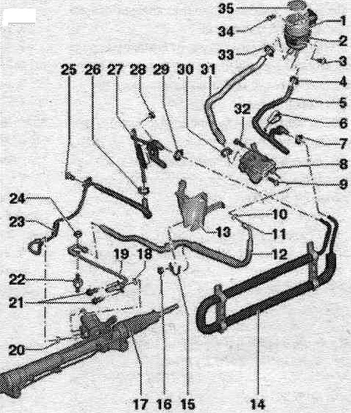
1. Expansion tank: take into account installation. position.
2. Bandage.
3. Bolt: 9 Nm.
4. Spring clamp: Remove and install with hose clamp pliers.
5. Return hose: from hydraulic oil cooler to expansion tank. tank; observe the installation position on the tank; observe the installation position on the hydraulic oil cooler.
6. Clamp.
7. Clamp: tighten with clamp pliers; replace when removed.
8. Hydraulic steering pump "V119": with vane pump control valve -(V119)-; the pump and control valve are one unit and are replaced together; fill the hydraulic fluid before installation. with oil.
9. Bolt: 20 Nm.
10. Sealing ring: replace when removed.
11. Union nut bolt: 38 Nm.
12. Pressure line: from the vane pump to the steering gear with hydraulic unit. Insert the pressure line all the way during installation.
13. Connecting element: engine bracket.
14. Hydraulic oil cooler: fixed to the condenser with a clip.
15. Mounting bracket.
16. Nut: 9 Nm.
17. Power steering.
18. Sealing ring: replace when removed.
19. Pressure line: tightening torque of union nut: 40 Nm; from the vane pump to the steering gear with hydraulic control. Insert the pressure line all the way during installation.
20. Sealing ring: replace when removed.
21. Bolt: 20 Nm.
22. Rubber cushion: 6 Nm.
23. Return line: from the power steering mechanism to the hydraulic oil radiator; observe the installation position on the tank; observe the installation position on the hydraulic oil cooler.
24. Nut: 6 Nm.
25. Bolt: 9 Nm.
26. Clamp: tighten with clamp pliers; replace when removed.
27. Return line: from the power steering mechanism to the hydraulic oil cooler. Fully insert the return line during installation.
28. Nut: 9 Nm.
29/30. Clamp: tighten with clamp pliers; replace when removed.
31. Suction hose: observe the installation position on the tank: observe the installation. position on the vane pump.
32. Bolt: 20 Nm.
33. Spring clamp: Remove and install using hose clamp pliers.
34. Bolt: 9 Nm.
35. Locking cap with measuring probe.
(A link to the original source is available on the website AudiManual.ru)