



Table of contents: Front panel ↓ Removal and installation side… ↓ Removal and installation the MMI… ↓ Removal and installation the MMI… ↓ Removal and installation the middle… ↓ Removal and installation the… ↓ Removal and installation the system… ↓ Removal and installation the… ↓ Removal and installation the… ↓ Removal and installation the upper… ↓
Front panel
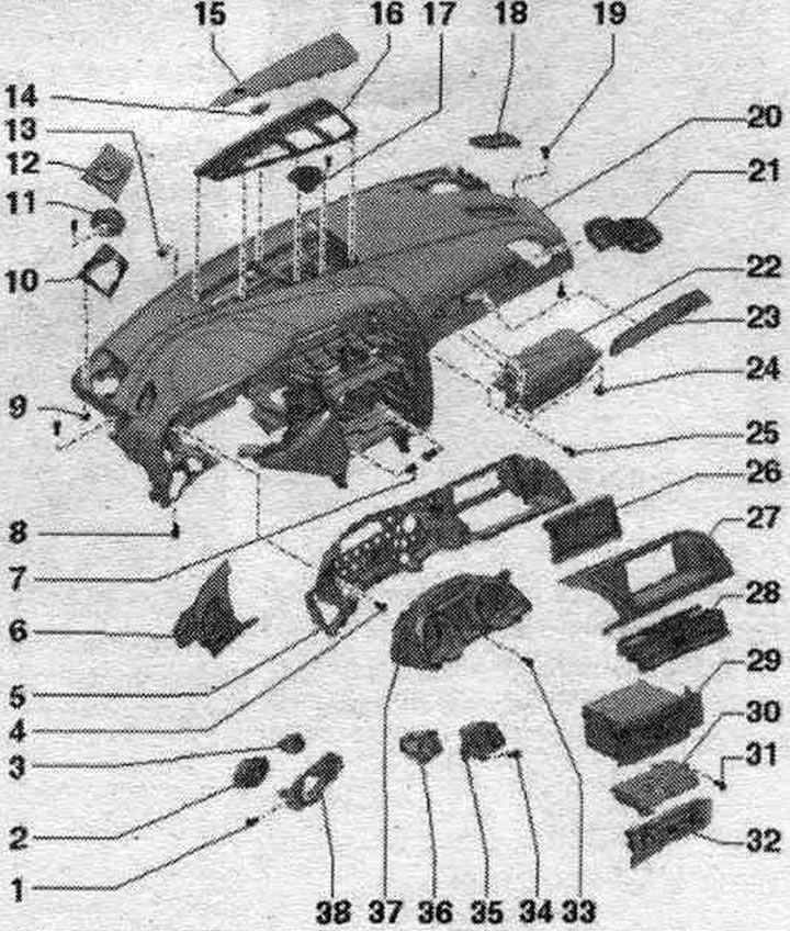
1. Bolt: 3 pcs.; 1.5 Nm.
2. Light switch "E1".
3. Headlight corrector regulator "E102".
4. Bolt: 6 pcs.; 3 Nm.
5. Instrument cluster retaining frame.
6. Left side deflector on the front panel: starting from mod. year 2012.
7/8. Bolt: 2 pcs.; 3 Nm.
9. Nut: 6 pcs.; 0.5 Nm.
10. Mount: for speaker.
11. Midrange speaker.
12. Speaker cover, side.
13. Nut: 6 pcs.; 0.5 Nm.
14. Sunlight intensity photo sensor "G107".
15. Speaker cover in the middle.
16. Upper middle defroster deflector.
17. Midrange speaker.
18. Upper side defroster deflector.
19. Bolt; 2 pcs.; 3 Nm.
20. Front panel.
21. Right side deflector on the front panel.
22. Airbag. from the lane. passenger: Locking and activation via key switch.
23. Decorative overlay.
24. Nut.
25. Bolt: 3 Nm.
26. MMI display.
27. Overlay; for MMI display; starting with mod. year 2012.
28. Front panel deflector in the middle.
29. Radio/navigation system.
30. Used front control panel, indication and information display "J523".
31/33. Bolt.
32. Used Climatronic "J255".
34. Bolt: 3 Nm.
35. Cover plate: for system switch. authorization of access and starting of the engine "E415".
36. System switch. authorization of access and starting of the engine "E415".
37. Instrument cluster.
38. Lighting control switch panel cover.
MMI display cover - from model year 2012
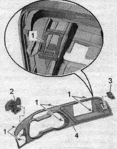
1. Staples - 6 pcs.
2. Removing and installing the left side deflectors on the front panel.
3. Hazard warning light switch "E229" with front passenger airbag deactivation indicator lamp "K145".
4. Removing and installing the MMI display cover.
Removal and installation side deflectors on the front panel
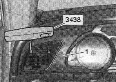
Carefully remove the front panel deflectors "1" on both sides using the puller "3438" one by one from the mounting hole on both sides. Option with illumination: Disconnect the plug connection of the front panel deflector.
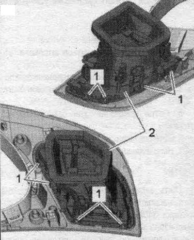
Since 2012 model year: Remove the MMI display cover. Carefully release the front panel deflector "2" from the latches "1" and remove it.
Installation in reverse order. When installing the front panel deflector, ensure that:. so that it fits into the duct correctly. Press the deflector into the mount. front panel hole until it stops.
Removal and installation the MMI display cover - up to model year 2011
Lift the cover "1" of the MMI display with wedge "3409" by the corners "arrow" and remove it. Disconnect the plug connection of the Airbag indicator lamp on the front side. passage, turn off "K145"/hazard warning light switch "E229" and remove the cover.
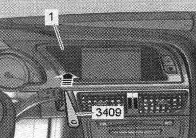
Installation in reverse order. Install the MMI display cover until it clicks into place.
Removal and installation the MMI display cover - from model year 2012
Set the steering wheel as far back and down as possible, using the full range of the reg. steering column position regulator. Unclip cover "1" of the MMI screen using wedge "T10383" from below the front panel of the "arrow".
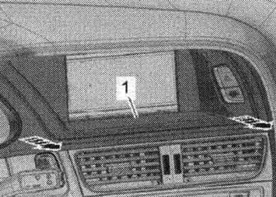
Unclip cover "1" of the MMI screen using wedge "T10383" from the bottom of the "arrow" instrument panel.
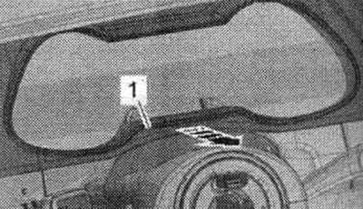
Unclip cover "1" of the MMI display using wedge "T10383" from the bottom of the front panel "arrow B". Carefully insert hook "T40207" between the slats and hook it onto the side of the deflector. Carefully unclip the deflector on the sides "arrow A".
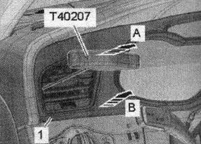
Carefully unclip cover "1" of the MMI display from the front panel of the "arrow." Disconnect the plug connection of the front panel air vent. Disconnect the Airbag indicator lamp connector on the front side. passage, turn off "K145"/hazard warning light switch "E229" and remove the MMI display cover.
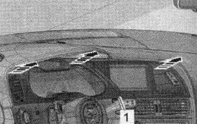
Installation is in reverse order, taking into account the following. Install the MMI display cover until it clicks into place.
Removal and installation the middle speaker cover
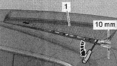
Remove and install the speaker cover very carefully, as it is easily damaged. Carefully loosen the speaker cover "1" with a small screwdriver from the rear clips "arrow" in relation to the direction of movement and lift it up approx. 10 mm. Do not lift the speaker cover any higher, as this will break the clips facing the direction of movement.
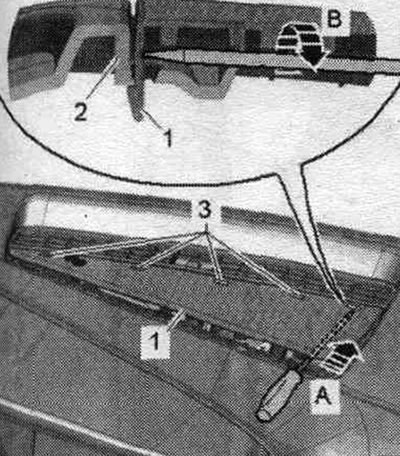
Insert a long screwdriver under the speaker cover in the forward direction "arrow A" until it touches the right front. retainer. Carefully turn the screwdriver around its axis "arrow B" so that the retainer tab "1" pops out of the guide "2". Repeat this operation on the remaining retainers "3".
Installation in reverse order. First, place the speaker cover on the front panel from the front and press until it clicks into place.
Removal and installation the lighting control switch panel trim
Remove the driver's side dashboard trim. Remove the driver's side dashboard trim. From 2012 model year: Remove the MMI display cover. Disconnect the instrument cluster slot trim from the dashboard. Remove the light switch. Option with headlight range control regulator: Remove headlight range control regulator "E102". Unscrew the "arrow" bolts and remove the light switch panel cover "1".
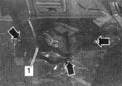
Installation in reverse order.
Removal and installation the system switch cover. access control and engine start right "E415"
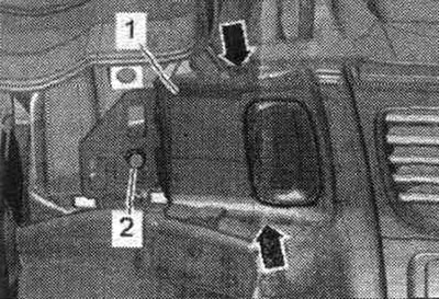
Remove the MMI display cover. Disconnect the instrument cluster slot trim from the front panel. Unscrew bolt "2" of cover "1".
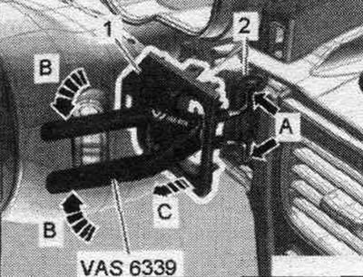
Insert the ignition switch removal pliers "VAS 6339" into the valve cover. Insert the ends of the ignition switch removal pliers "VAS 6339" into both holes "arrow A" of the switch "2" for access control and engine start right "E415". Squeeze them "VAS 6339" "arrows B", which will cause the ends of the pliers to spread apart and the locking tabs of the lining to be released. Squeeze the "VAS 6339" with one hand and remove the "1" "arrow C" cover with the other. Use the "VAS 6339" ignition lock removal pliers only for unlocking; remove the cover manually.
Installation in reverse order.
Removal and installation the instrument cluster frame
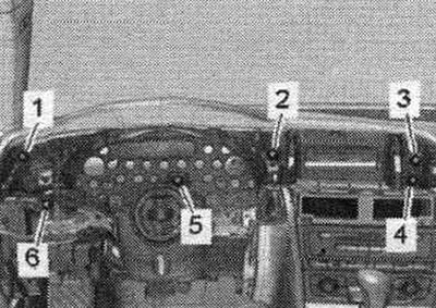
Remove the instrument cluster. Remove the light control switch panel cover. Remove the MMI display. Unscrew bolts "1...6" and remove the frame.
Installation in reverse order.
Removal and installation the instrument panel
Set the steering wheel as far back and down as possible, using the full range of the reg. steering column position regulator. Move the seats all the way back and position their backrests at a 45° angle. Turn on the ignition. Disconnect the battery ground cable with the ignition on. Remove the driver's airbag module. Remove the steering wheel. Remove the instrument cluster slot trim. Remove the front panel trim from the driver's side. Disconnect the plug connection of the switch. lighting control. Option with headlight range control: Disconnect the plug connection of the headlight range control "E102". Remove the side deflector of the front panel. Remove the MMI display cover. Remove the MMI display. Remove the instrument cluster. Disconnect the plug connection of the access control switch and engine start right. Remove the front panel deflector in the middle. Remove the radio/navigation system. Remove the used Climatronic "J255". Remove the used front control panel, display and information "J523". Remove the center console.
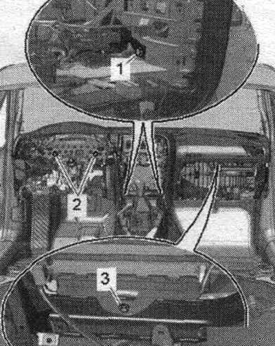
Remove the glove compartment. Disconnect the front passenger airbag plug connection. Speaker version: Remove the mid-range speaker in the middle of the front panel. Remove the "G107" solar radiation intensity sensor. Speaker version: Remove the side midrange speaker from the front panel. Remove the upper trim of the A-pillars. Remove the glove compartment holder. Disconnect and remove the front panel stretcher. Unscrew the bolts "1" of the front panel on the left and right top near the A-pillar. Unscrew the bolts "2" on the left and right bottom of the front panel. Unscrew the "arrow" bolts of the left and right air ducts of the front panel.
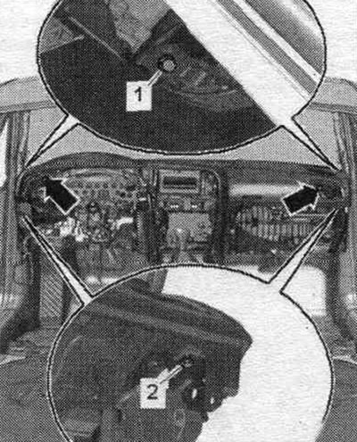
Unscrew the bolts "1" of the front panel on the central pipe of the front panel in the middle. Unscrew the bolts "2" of the front panel on the central pipe of the front panel on the right. Unscrew bolt "3" of the front panel on the central pipe of the front panel on the left.
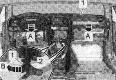
Carefully remove the front panel "1" from the front panel center tube backwards "arrows A". At the same time, detach the front panel from the holder "2" "arrow B". Remove the front panel from the vehicle interior and place it on a soft pad.
Installation
Installation in reverse order. Install the front panel and insert the plug connections of the solar radiation intensity sensor "G107" and the speaker through the holes in the front panel. Check if there are rubber shock absorbers "4" on the clamp "3" of the lower shelf of the windshield frame. When sliding out the front panel "1", ensure that the clips engage with the box profiles on the bottom of the front panel.
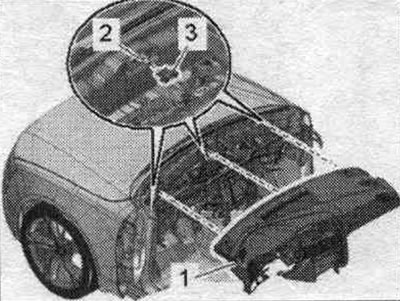
Please note that the plug connections must be inserted all the way until they click into place. Align the front panel and tighten the bolts. Connect the battery ground cable with the ignition on.
Removal and installation the upper center defroster deflector
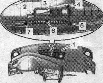
Remove the front panel. Unscrew nuts "2...7" on the bottom side of the front panel. Remove the middle upper defroster deflector "1" from the front panel in an upward direction.
Installation
Installation in reverse order. When tightening the nuts, ensure that there is an equal gap between the top of the front panel and the top edge of the upper middle defroster vent, as well as an even gap around the perimeter.
(The article was copied from the website «audimanual.ru»)