Repair Chevrolet Repair Toyota Repair Honda Repair AvtoVAZ Repair Mercedes-Benz Repair BMW Repair Opel
Home  |  Contacts  |  Sitemap  |    
English Русский
Български
Беларускі
Український
Српски
Hrvatski
Română
Polski
Slovenský
Magyar
AudiManual.ru


  • AUDI 80
  • AUDI 100
  • AUDI A3
  • AUDI A4
  • AUDI A6
  • AUDI A8
  • AUDI Q
  • OTHER
  • ARTICLES
B8 (2007-2015) B7 (2004-2008) B6 (2000-2006) B6 (2000-2006, petrol) B5 (1994-2001) B5 (1994-2001, petrol)

Storage compartments/pads (Audi A4 B8)

  • Home
  • Audi A4
  • B8 (2007-2015)
  • Body
  • Interior
  • Storage compartments/pads
            0
Table of contents: Driver's side dashboard trim ↓ Steering column switch module trim ↓ Removal and installation the… ↓ Removal and installation the upper… ↓ Removal and installation the lower… ↓ Glove compartment ↓ Removal and installation the glove… ↓ Removal and installation the front… ↓ Removal and installation the glove… ↓ Removal and installation the glove… ↓ Removal and installation of brakes.… ↓

Driver's side dashboard trim
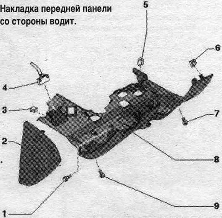


1. Bolt: 3 Nm.

1. Bolt: 3 Nm.
2. Side cover: for front panel.
3. Clamp: Insert into the footrest.
4. Plug connector, 16-pin "T16": diagnostic connector.
5. Clamp: insert into the air conditioning unit.
6. Spring clip: for the driver's side front panel trim.; press into the front panel.
7. Bolt: 3 Nm.
8. Front panel trim on the driver's side.
9. Bolt: 3 Nm.


Removal


Remove the driver's side front panel trim. Unscrew bolt "1" on the side. Unscrew bolts "3" from the bottom. Remove driver's side front panel trim "2" from its clips by lifting it by the top edge with wedge "3409" from the front panel. Disconnect the 16-pin connector "T16" (diagnostic plug). Option with space lighting. for legs: disconnect the plug connection. Remove the front panel trim from the driver's side.
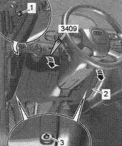


Remove the driver's side front panel trim. Unscrew bolt «1» on the side. Unscrew bolts «3» from the…


Installation


Installation in reverse order. Insert the front panel trim "1" from below into the clip "3" on the footrest and the clip "2" on the air conditioner "arrows".
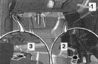
Installation in reverse order. Insert the front panel trim «1» from below into the clip «3» on the…


Steering column switch module trim


1. Slotted trim: instrument cluster.

1. Slotted trim: instrument cluster.
2. Upper trim of the steering column switch module.
3. Bolts: 2.0 Nm.
4. Lower trim of the steering column switch module.
5. Bolt: 2.0 Nm.
6. Handle: for adjusting the position of the steering column.
7. Bolt: 3 Nm.


Removal and installation the instrument cluster slot trim


Set the steering wheel as far back and down as possible, using the full range of the reg. steering column position regulator. From the 2012 model year: Remove the MMI display cover. Remove the cover on the joint "1" of the instrument cluster from the clips using wedge "3409" from the front panel of the "Arrow A". Using a small flat-blade screwdriver, carefully remove the cover on the joint from the fasteners of the upper trim of the steering column switch module of the "Arrow B".
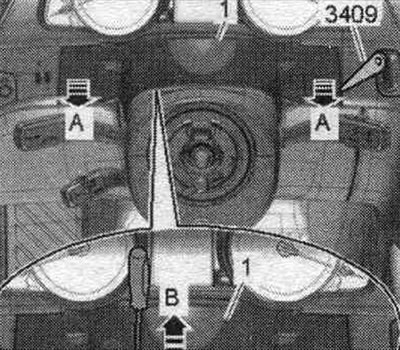
Set the steering wheel as far back and down as possible, using the full range of the reg. steering…


Installation in reverse order. Press the cover onto the joint until the brackets are fully snapped into place at the attachment points.

Removal and installation the upper trim of the steering column switch module


Set the steering wheel as far back and down as possible, using the full range of the reg. steering column position regulator. Using a small flat-blade screwdriver, carefully remove the slot cover "2" from the fasteners of the upper trim "1" of the steering column switch module "arrow A". Turn the steering wheel 90° from the straight-ahead position. Carefully pry the upper trim panel away from the lower trim panel "3" of the steering column switch module "arrow B" using a small flat-head screwdriver. Unclip the upper trim panel from the lower trim panel of the steering column switch module and remove it.
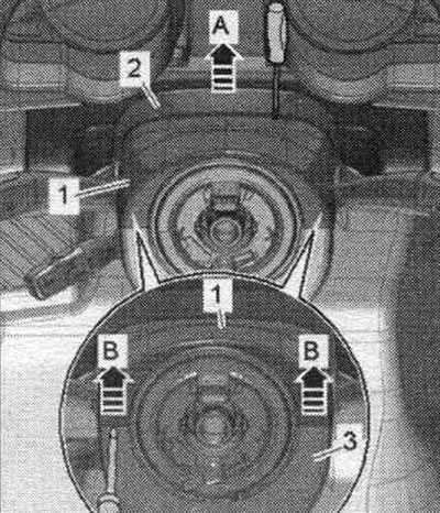


Set the steering wheel as far back and down as possible, using the full range of the reg. steering…


Installation


Installation in reverse order. First, secure the upper trim "1" to the lower trim "arrow A". Make sure that the projection of the lower trim engages in the notch on the locking tab of the upper trim "arrow B".
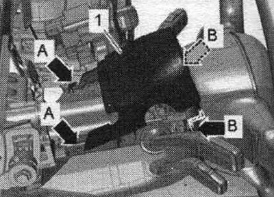
Installation in reverse order. First, secure the upper trim «1» to the lower trim «arrow A». Make…


Removal and installation the lower trim of the steering column switch module


Remove the upper trim panel of the steering column switch module. Turn the steering wheel 90° from the straight-ahead position. Remove bolts "1" and "2." If bolts "1" and "2" are inaccessible, the steering wheel must be removed for further work. Unscrew bolt "4" and remove the lower trim "3" of the steering column switch module.
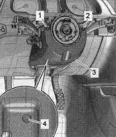
Remove the upper trim panel of the steering column switch module. Turn the steering wheel 90° from…


Installation in reverse order.


Glove compartment
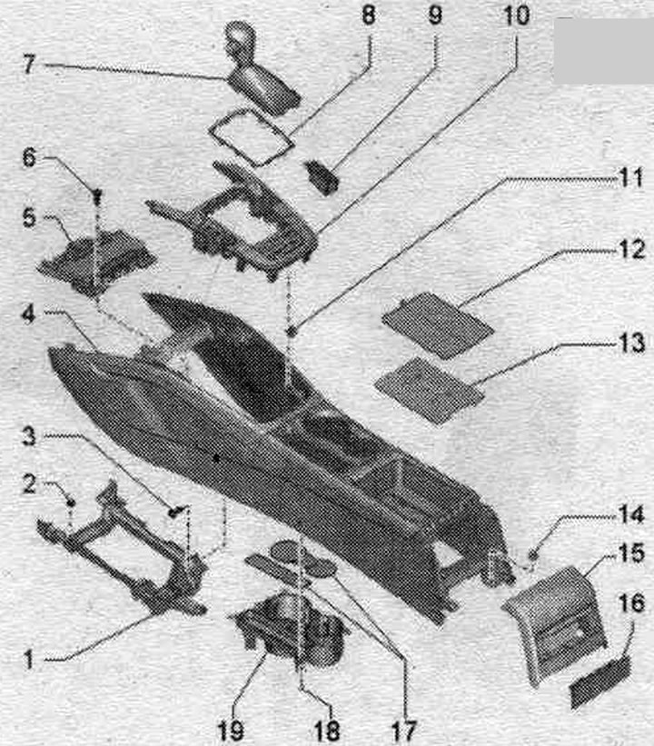


1. Glove compartment light «W6».

1. Glove compartment light "W6".
2. Ceiling light for space lighting. for legs.
3. Front panel trim from the front side. passage.
4. Bolt: 2 pcs.; 3 Nm.
5. Hinge bolt: for fixing the glove box lid.
6. Rubber stop for glove compartment; 6 pcs.
7. Glove compartment.
8. Bracket.
9. Glove box lid damping element: with glove box light switch "E26".
10. Hinge bolt.
11. Bolt: 3 Nm.
12. Bolt: 3 or 5 pieces; 3 Nm.
13. Fastening the bolt.
14. Switch with lock for disabling the front passenger airbag. "E224".
15. Holder.
16. Bolt: quantity depending on the configuration or variant for a specific country; 3 Nm.
17. Glove compartment lid.
18. Key for opening the glove compartment.
19. Glove box lid stop buffer.


Removal and installation the glove compartment key


Through the "arrow" hole on the side of the glove box lid, press the glove box opener stopper with the "T40011" pin.
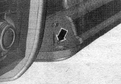
Through the «arrow» hole on the side of the glove box lid, press the glove box opener stopper with…


At the same time, press the 2nd stopper "1" on the side of the glove box opener with a screwdriver. Remove the glove box opening key from the glove box lid "arrow".
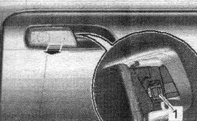


At the same time, press the 2nd stopper «1» on the side of the glove box opener with a screwdriver.…


Installation in reverse order. Install the glove box opener until it clicks into place.

Removal and installation the front panel trim on the front passenger side


Loosen the fasteners and remove the front panel trim "1" from the front side. passage, from the glove compartment "arrow".
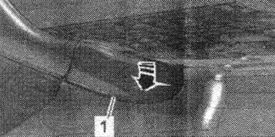
Loosen the fasteners and remove the front panel trim «1» from the front side. passage, from the…


Installation in reverse order. Install the front panel trim from the front side. passage until it clicks.

Removal and installation the glove box


ATTENTION! When working on a vehicle with a key switch to deactivate the front passenger airbag "E224", observe safety regulations. when working with pyrotechnic products.


Turn on the ignition. Disconnect the battery ground cable with the ignition on. Option with a storage compartment in the glove box: use a screwdriver to press the left and right "arrow" latches and remove the storage compartment from the glove box. Option for a CD drive: remove the CD drive.
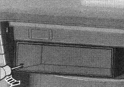


Turn on the ignition. Disconnect the battery ground cable with the ignition on. Option with a…


Depending on the configuration or export option: unscrew the upper bolt "1", installed at an angle. Export version with horizontal shock absorber: unscrew bolt "2".
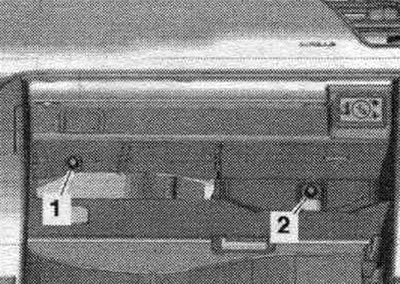
Depending on the configuration or export option: unscrew the upper bolt «1», installed at an angle.…


Remove the front panel trim from the front side. passage... Open the glove compartment lid and unscrew the "arrow" bolts. Do not completely remove the glove compartment so that you can disconnect the plug connection from the central connector.
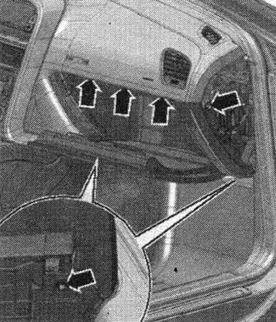
Remove the front panel trim from the front side. passage... Open the glove compartment lid and…


Installation in reverse order. Connect the plug connection until it clicks into place. Turn on the ignition. Connect the battery ground cable with the ignition on.


Removal and installation the glove box lid


Remove the glove compartment. Remove the hinge pin from the brake. element. Place the glove compartment with the top side up on a soft lining. Knock out the hinge bolts on the left and right using a 4 mm Allen key "pos. 1" (or other suitable tool) "Arrow". Remove the glove compartment cover "2" from the glove compartment.
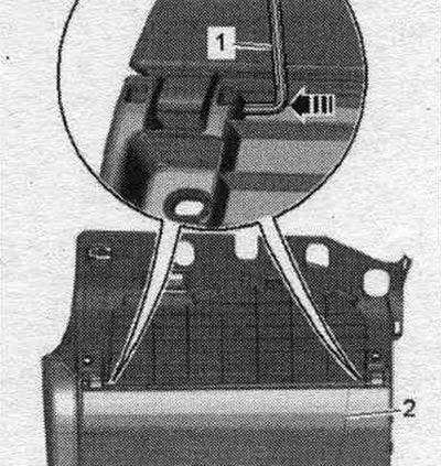
Remove the glove compartment. Remove the hinge pin from the brake. element. Place the glove…


Installation in reverse order.

Removal and installation of brakes. glove compartment lid element


Turn off the ignition. Remove the side trim of the front panel from the front side. passage.. Unfasten and move aside the retainer of the right front panel. Disconnect plug connection "3". Remove hinge bolt "1". Unclip switch "2" by turning it counterclockwise, "arrow", and remove it.
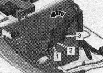
Turn off the ignition. Remove the side trim of the front panel from the front side. passage..…


Installation in reverse order. Install the front panel clips on the right.

The original source of the article can be found on the website: Audimanual.ru
The article was checked by auto expert Timur Bazhenov
This article is available at russian, bulgarian, belarusian, ukrainian, serbian, croatian, romanian, polish, slovak, hungarian

Share information:
Previous articles
Audi A4 B8: Interior
Next articles

Center console — removal and installation
Front center armrest — removal and installation
Rearview mirror — removal and installation
Front panel — removal and installation


Similar articles on other Audi car models:
Ashtrays and storage box Audi 80 B3 (1986-1991, petrol)
Front Brake Disc Pads — Checking and Replacing Audi 100 C3 (1982-1990, diesel)
Replacing the front brake pads Audi A3 Type 8L (1996-2003)
Replacing the front brake pads Audi A6 C5 (1997-2004)
Checking the front brake pads Audi A8 D2 (1994-2002)
Storage compartments/pads Audi Q5 Type 8R (2008-2017)
Brake pads — thickness check Audi A2 (1999-2005)
Link to this page in different formats


Visitor comments

No comments yet


How much will 24 + 24 =


A4(B8, 2007-2015) 
  • General information
  • Operating instructions
  • Power unit
  • Petrol engines 1.8 l
  • Petrol engines 1.8/2.0 l
  • Petrol engines 3.0 l
  • Petrol engines 3.2 l
  • Fuel system (petrol)
  • Diesel engines 2.0 l (CA*)
  • Diesel engines 2.0 l (CJCB)
  • Diesel engines 2.7/3.0 l
  • Diesel engines 3.0 l
  • Fuel system (diesel)
  • Transmission
  • Manual gearbox 0B1
  • Manual gearbox 0B2
  • Manual gearbox 0B3
  • Manual gearbox 0B4
  • Automatic transmission 0B5
  • Automatic transmission 0B6
  • Automatic transmission 0AW
  • All-wheel drive system
  • Chassis
  • Front suspension
  • Rear suspension
  • Brake system
  • Steering system
  • Body
  • Exterior
  • Interior
  • Seats
  • Doors, locks and windows
  • Security system
  • Heating and air conditioning
  • Electrical equipment
  • Audio system
  • Power devices
  • Equipment and devices
  • Lighting and lamps
  • Electrical circuits
 
A4(B7, 2004-2008) 
  • General information
  • Introduction to manual
  • Troubleshooting
  • Operating instructions
  • Maintenance
  • Power unit
  • Petrol engines 2.0 (ALT)
  • Petrol engines 2.0 (TFSI)
  • Petrol engines 1.8 (MPI)
  • Diesel engines
  • Cooling system
  • Air conditioner
  • Fuel and exhaust system
  • Ignition system
  • Starting and charging
  • Transmission
  • Clutch
  • Manual gearbox
  • Automatic gearbox
  • Drive shafts
  • Chassis
  • Brake system
  • Front suspension
  • Rear suspension
  • Steering
  • Body
  • Exterior
  • Interior
  • Electrical equipment
  • Equipment and devices
  • Lighting and signaling
  • Windscreen wipers and washers
  • Electrical diagrams
  • Electrical diagrams (since 2007)
 
A4(B6, 2000-2006) 
  • General information
  • Vehicle Description
  • User manual
  • Maintenance
  • Power unit
  • Gasoline engine
  • Diesel engine
  • Lubrication system
  • Cooling system
  • Supply system
  • Injection system
  • Exhaust system
  • Ignition and control
  • Transmission
  • Gear box
  • Clutch and drive shafts
  • Chassis
  • Brake system
  • Car suspension
  • Steering
  • Body
  • Heating and ventilation
  • Exterior (external elements)
  • Interior (internal elements)
  • Electrical equipment
  • Power devices
  • Lighting and appliances
  • Electrical circuits
 
A4(B6, 2000-2006, petrol) 
  • General information
  • Introduction to the guide
  • Car care
  • Power unit
  • Engine repair
  • Lubrication system
  • Cooling system
  • Injection and control system
  • Ignition system
  • Power and exhaust system
  • Transmission
  • Clutch and drive shafts
  • Car gearbox
  • Chassis
  • Suspension and wheels
  • Steering
  • Brake system
  • Body
  • Interior
  • Exterior
  • Electrical equipment
  • Equipment and devices
  • Lighting and signaling
  • Power devices
  • Electrical circuits
 
A4(B5, 1994-2001) 
  • General information
  • Introduction to the guide
  • Car care
  • Maintenance (gasoline)
  • Maintenance (diesel)
  • Power unit
  • Gasoline engines
  • Diesel engines
  • Engine overhaul
  • Cooling system
  • Fuel injection (gasoline)
  • Fuel system (diesel)
  • Exhaust system
  • Ignition system
  • Transmission
  • Clutch
  • Mechanical gearbox
  • Automatic gearbox
  • Drive shafts
  • Chassis
  • Brake system
  • Car suspension
  • Steering
  • Body
  • Exterior
  • Interior
  • Doors, locks and windows
  • Heating and ventilation
  • Electrical equipment
  • Power devices
  • Equipment and devices
  • Electrical circuits
 
A4(B5, 1994-2001, petrol) 
  • General information
  • Vehicle description
  • Maintenance
  • Power unit
  • Engine repair
  • Turbocharging
  • Exhaust system
  • Cooling system
  • Ignition system
  • Fuel system
  • Motronic injection system
  • MPI and MPFI injection system
  • Transmission
  • Clutch
  • Gearbox and shafts
  • Chassis
  • Steering
  • Car suspension
  • Brake system
  • Wheels and tires
  • Body
  • Heating and ventilation
  • Body parts
  • Electrical equipment
  • Fuses and relays
  • Power devices
  • Lighting and lamps
  • Tools and devices
  • Electrical circuits
 
AudiManual.ru © 2017-2026 · Mobile version · Feedback · Sitemap: EN BG BY UA RS HR RO PL SK HU · Site search · News and articles
80 B2 · 80 B3 petrol · 80 B3 · 80 B4 · 100 C3 diesel · 100 C3 petrol · 100 C3 · 100 C4 petrol · 100 C4 · A3 Type 8L · A4 B5 petrol · A4 B5 · A4 B6 petrol · A4 B6 · A4 B7 · A4 B8 · A6 C4 · A6 C5 · A6 C5 Allroad · A8 D2 · Q5 Type 8R · Q7 Typ 4L · Audi A2 ·
This site uses cookies 🍪. Click the button to accept this fact.