
Table of contents: Removal the front panel cover on the… ↓ Installation ↓ Removal the cover for the headlight… ↓ Installation ↓ Cutting the cover for the headlight… ↓ Removal the instrument cluster slot… ↓ Installation ↓ Removal the upper trim of the… ↓ Installation ↓ Removal the lower trim of the… ↓ Removal the key to open the glove box ↓ Removal the front panel trim on the… ↓ Removal the glove pocket ↓ Removal the glove compartment ↓ Installation ↓ Removal the glove compartment lid ↓ Removal the glove compartment lid… ↓
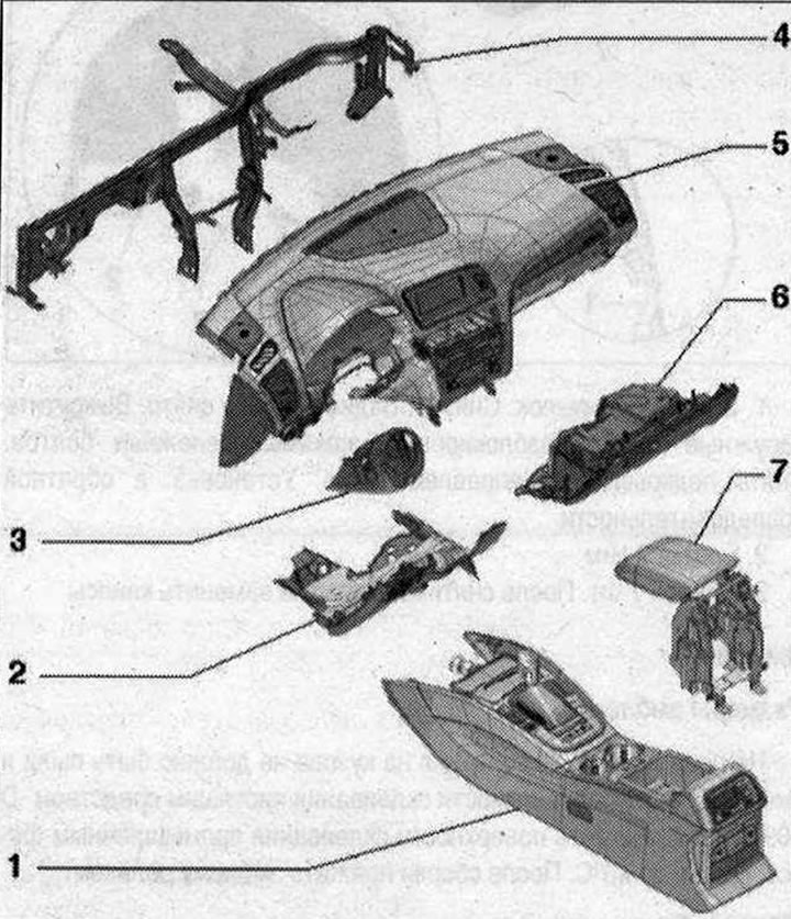
Brief description, compartments/pads 1. Center console; 2. Driver's side front panel trim; 3. Steering Column Switch Module Trim; 4. Central pipe for the front panel; 5. Front panel; 6. Glove box; 7. Front center armrest
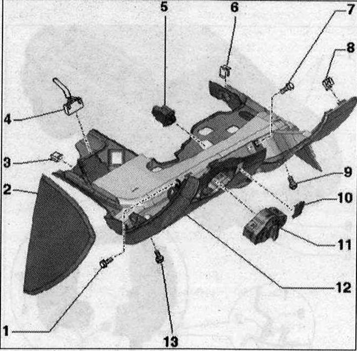
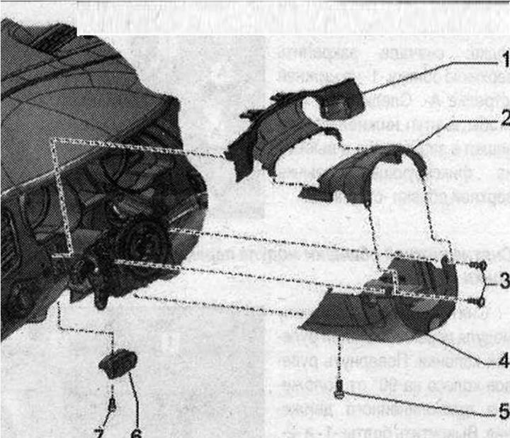
Driver's side front panel cover 1/7/9. Bolt. 3 Nm; 2. Side trim for front panel; 3. Clamp. Insert into the footrest; 4. Plug connector, 16-pin "T16". Diagnostic connector; 5. Headlight corrector regulator "E102"; 6. Clamp. Insert into the air conditioning unit; 8. Spring clip for driver side dashboard trim, 3 pcs. Press into dashboard; 10. Overlay for headlight corrector regulator "E102"; 11. Light switch "E1"; 12. Driver's side front panel trim (different designs depending on the market). Option kit with headlight corrector regulator "E102": after replacing the front panel trim on the driver's side, cut an opening for the headlight corrector regulator; 13. Bolt. 3 Nm
Removal the front panel cover on the driver's side
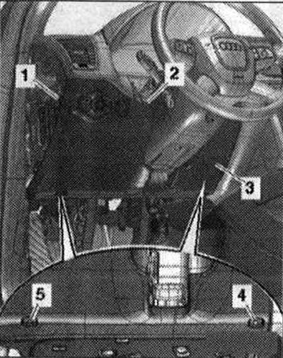
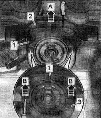
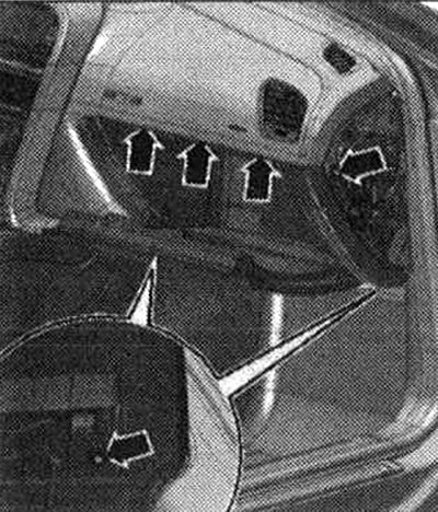
Switch off all electrical consumers. Remove the ignition key. Remove the side trim of the front panel on the driver's side. Disconnect the slot trim of the instrument cluster from the front panel. Unscrew the upper screws "1, 2". Unscrew the lower screws "4,5".
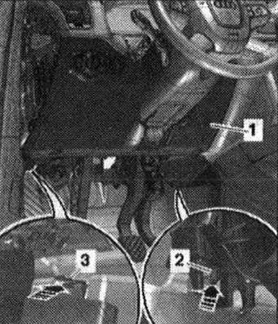
Remove the front panel trim "3" from the driver's side from the retainers by lifting it by the upper edge with a wedge "3409" from the front panel. Disconnect the light switch connectors. Option complete with headlight corrector regulator "E102": disconnect the electrical connector. Disconnect the 16-pin connector "T16" (diagnostic plug). Option kit with footwell lighting: Disconnect the electrical connector. Remove the driver's side dashboard trim.
Installation
Installation in reverse order: insert the front panel trim "1" from below into the clamp "3" on the footrest and clamp "2" on the air conditioner "arrow".
Fix the front panel trim along the top edge of the front panel.
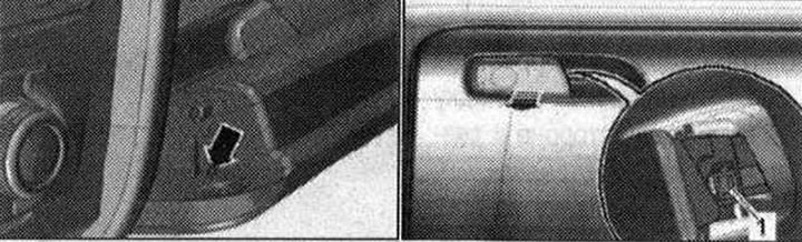
Removal the cover for the headlight corrector regulator "E102"
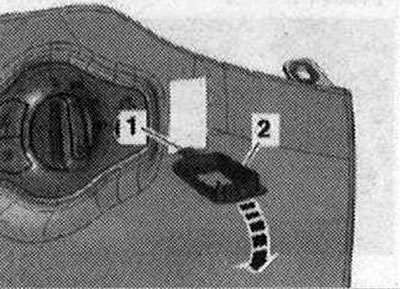
Remove the driver's side front panel trim. Remove the headlight corrector adjuster. Disconnect the trim "2" on the upper side and turn it forward "arrow".
Remove the trim from the opening of the front panel trim on the driver's side.
Installation
Installation in reverse order: insert guide tabs "1" into the opening of the front panel on the driver's side and press until an audible click is heard.
Cutting the cover for the headlight corrector regulator "E102" in the front panel
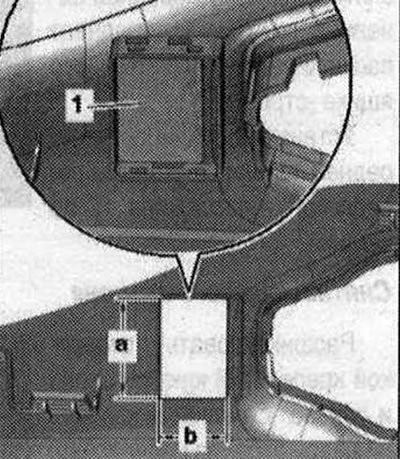
The original part is supplied with the driver's side dashboard trim without the opening for the headlight range adjuster "E102". In the complete version with the headlight range adjuster "E102", it is necessary to make an opening in the new driver's side dashboard as described below. Cut out the opening for the headlight range adjuster in the marked area "1" in the driver's side dashboard with the dimensions "a" and "b", as shown in the figure.
Dimension "a" = 35.5 mm. Dimension "b" = 23.5 mm
Install the headlight range adjuster trim. Install the headlight range adjuster. Install the driver's side dashboard trim.
Steering Column Switch Module Trim 1. Slotted overlay; 2. Steering Column Switch Module Upper Trim; 3. Bolts. 2.0 Nm; 4. Steering Column Switch Module Lower Trim; 5. Bolt 2.0 Nm; 6. Handle for adjusting the position of the steering column; 7. Bolt. 3 Nm
Removal the instrument cluster slot trim
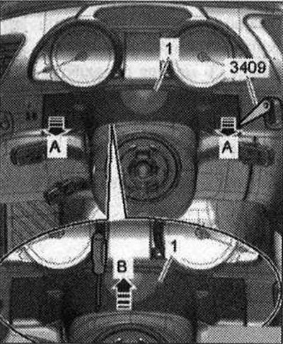
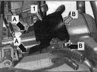
Set the steering wheel as far back as possible, using the full range of adjustment of the steering column position regulator. Remove the cover on the joint "1" of the instrument cluster from the clamps with wedge "3409" from the front panel "arrows A".
Using a small flat-blade screwdriver, carefully remove the joint cover from the upper trim fasteners of the "arrow B" steering column switch module.
Installation
Installation in reverse order: press the cover plate onto the joint until the brackets are fully snapped into place at the attachment points.
Removal the upper trim of the steering column switch module
Set the steering wheel as far back as possible, using the full range of adjustment of the steering column adjuster. Using a small flat-blade screwdriver, carefully remove the cover on the joint "2" from the fastenings of the upper trim "1" of the steering column switch module "arrow A".
Turn the steering wheel 90° from the straight-ahead position. Carefully pry the upper trim away from the lower trim "3" of the steering column switch module "arrow B" with a small flat-blade screwdriver. Unclip the upper trim from the lower trim of the steering column switch module and remove.
Installation
Installation in reverse order: first fasten the upper trim "1" to the lower trim "arrow A". Make sure that the projection of the lower trim engages in the recess on the fixing tongue of the upper trim "arrow 2".
Removal the lower trim of the steering column switch module
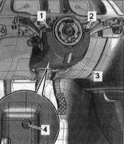
Remove the upper trim of the steering column switch module. Turn the steering wheel 90° from the straight-ahead position. Unscrew bolts "1" and "2". If screws "1" and "2" are not accessible, the steering wheel must be removed to perform the following work. Unscrew bolt "4" and remove the lower trim "3" of the steering column switch module.
Installation in reverse order.
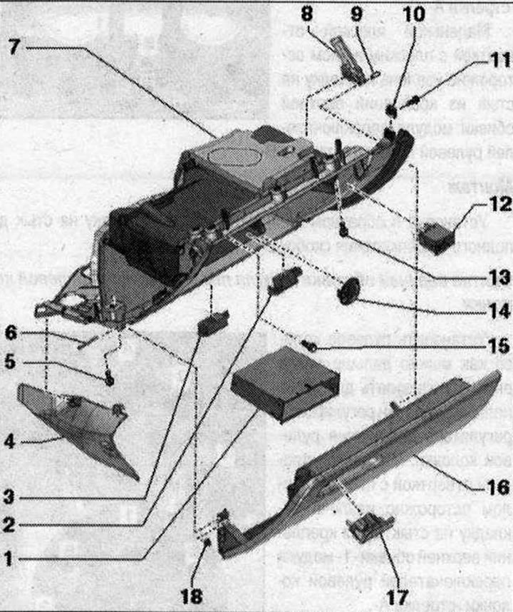
Glove box parts and components 1. Storage compartment; 2. Glove compartment light "W6"; 3. Footwell light; 4. Front panel trim on the front passenger side; 5. Bolt. 2 pcs. 3 N·m; 6. Hinge bolt for fastening the glove box lid; 7. Glove box; 8. Damping element of the glove compartment lid with the glove compartment light switch "E26"; 9. Hinge bolt; 10. Bracket; 11/15. Bolt. 3 Nm; 12. Switch with lock for disabling the front passenger airbag "E224"; 13. Bolt. 4 or 5 pieces depending on the export option. 3 Nm; 14. Cold Air Deflector/Sub-Cover; 16. Glove box lid; 17. Key for opening the glove compartment; 18. Glove box lid stop buffer
Removal the key to open the glove box
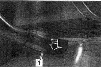
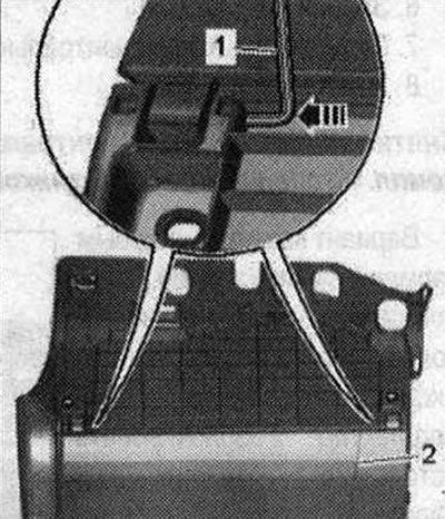
Through the hole "arrow" on the side of the glove box lid, press the glove box opener stopper with the pin "T40011".
At the same time, press the 2nd stopper "1" on the side of the glove box opener with a screwdriver. Remove the glove box opening key from the glove box lid "arrow".
Install the glove box opener until it clicks into place.
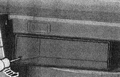
Removal the front panel trim on the front passenger side
Loosen the fasteners and remove the front panel trim "1" from the front passenger side from the glove compartment "arrow".
Install the front panel trim on the front passenger side until it clicks into place.
Removal the glove pocket
Unfasten the fastening hook on the left and right "arrow" with a screwdriver and remove the storage compartment from the glove box.
Press the storage compartment until it clicks.
Removal the glove compartment
Attention! When working on a car with a key switch for disabling the front passenger Airbag "E224", observe safety regulations when working with pyrotechnic products.
Turn on the ignition. Disconnect the battery ground cable with the ignition on.
Option complete with storage compartment in the glove box with tire: remove the storage compartment.
Option complete with CD drive: remove CD drive.
Depending on the kit or export option: unscrew the top bolt installed at an angle.
Export version with horizontal shock absorber: unscrew bolt "2".
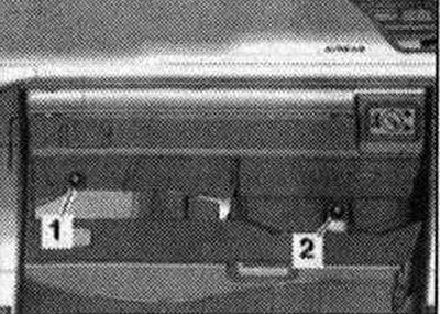
Remove the front panel trim from the front passenger side. Open the glove compartment lid and unscrew the "arrow" screws.
The number of bolts depends on the export version. Before handling pyrotechnic parts and restraint systems (for example, by disconnecting the plug connector) the mechanic must "discharge himself of static charge." To do this, for example, you can briefly touch the door lock. Do not completely remove the glove box so that you can disconnect the plug from the central socket.
Option kit with connector for connecting external audio sources "R199": disconnect the connector for connecting external radio signal sources "R199".
Installation
Installation in reverse order: install the plug connector until it clicks. Turn on the ignition. Connect the battery ground cable with the ignition on. If the Airbag "K75" indicator lamp signals a malfunction after installation, query the fault memory, clear it and re-query it.
Removal the glove compartment lid
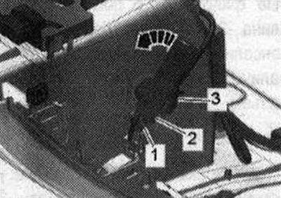
Remove the glove box. Remove the hinge pin from the brake element. Place the glove box with the top side on a soft pad. Knock out the hinge bolts on the left and right with a 2 mm Allen key "pos. 1" (or other suitable tool) "arrow". Remove the glove box cover "2" from the glove box.
Installation - in reverse order.
Removal the glove compartment lid damper
Remove the glove box. Disconnect the electrical connector "3". Remove the hinge bolt. Unscrew the brake element "2" by turning it counterclockwise "arrow" and remove it.
Installation in reverse order.
(Text provided by the online resource: «AudiManual»)