
Table of contents: Glass frame and window lifter ↓ Removal and installation hinges ↓ Door adjustment ↓ Door locking elements ↓
Note: The description is given using the front door as an example; for the rear doors, the procedures are similar.
Glass frame and window lifter
1. The details of the glass frame and window lifter installation are shown in the illustration.
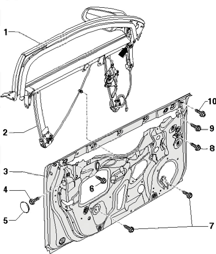
6.1. Glass frame and window lifter installation details 1. Glass frame; 2. Window lifter; 3. Front door; 4. Bolt, 32 Nm; 5. Plug; 6. Flange bolt, 32 Nm; 7. Flange bolt, 6Nm; 8. Bolt, 10 Nm; 9. Flange bolt, 32 Nm
2. Remove the door trim panel (see Part B) and disconnect the connectors.
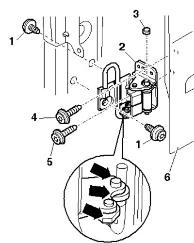
3. Remove the bolts (2 in the illustration) and remove the window lift motor (1).
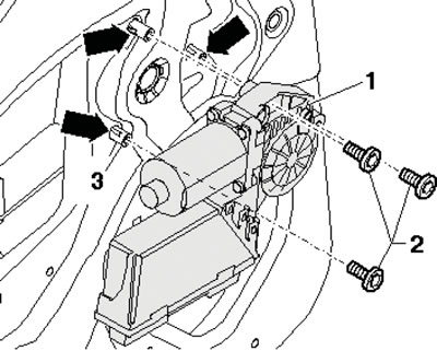
6.3. Fastening of electric window motor
4. Remove the bolts (7, 4, 8, 10, 6 and 9 in Illustration 6.1) and remove the glass frame together with the window lifter from the door.
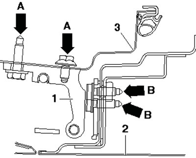
5. If necessary, remove the bolts (3 in the illustration) and remove the window lifter from the frame. Lower the glass if necessary. Remove the bolts (5) and separate the glass from the window lifter.
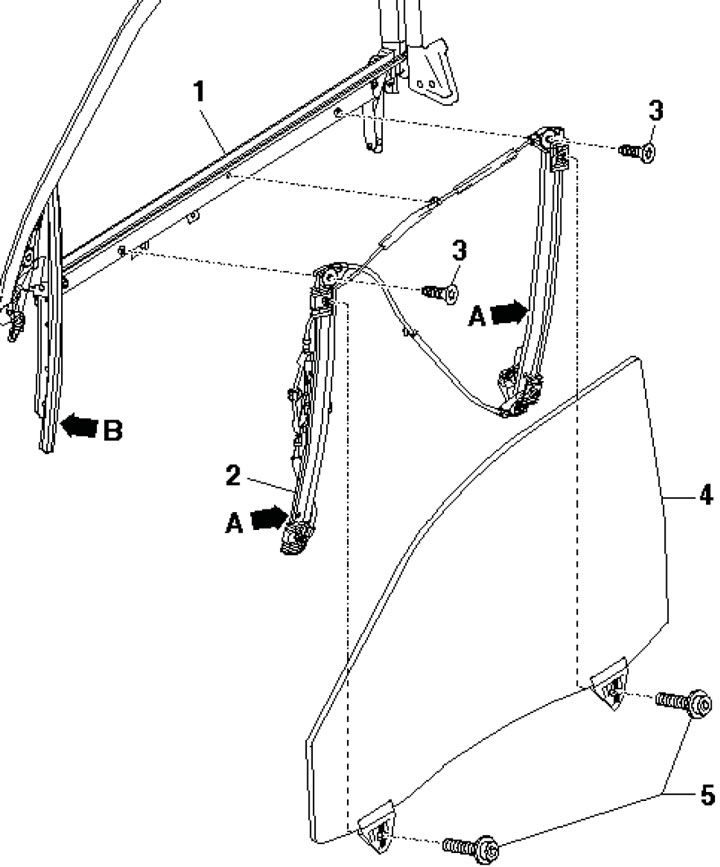
6.5 Fastening of glass and window lifter 1. Glass frame; 2. Window lifter; 3. Bolt, 6 Nm; 4. Glass; 5. Bolt, 4 Nm
6. Installation is performed in the reverse order of dismantling the components. Please note the following.
7. Two guides (And in illustration 6.5) must be positioned parallel to the guide (B).
8. Before installation, pull the glass halfway into the frame. Insert the frame with the door, secure the upper half of the door seal and lightly tighten the bolts (6, 9, 3, 8 and 10 in Illustration 6.1). Tighten the bolts (6 and 9) by hand and press the top of the frame (1) slightly inward. Tighten the bolts (4, 8, 6 and 9) with a force of 32 Nm, and the bolt (10) - with a force of 10 Nm.
Tighten the locking bolt (arrow) in the frame to 32 Nm.
Removal and installation hinges
8. The details of the upper hinge fastening are shown in the illustration.
6.8. Upper hinge fastening details 1, 4. Bolt T45, 32 Nm; 2. Upper loop; 3. Plug; 5. Fitting bolt T45, 32 Nm
9. The details of the lower hinge fastening are shown in the illustration.
6.9 Upper hinge fastening details 1, 4. Bolt T45, 32 Nm; 2. Bottom loop; 3. Plug; 5. T45 fitting bolt, 32 Nm; 6. Front door
Door adjustment
10. Longitudinal adjustment is carried out by loosening the bolts (And in the illustration) pillars A on the upper and lower hinges (1) and the door sliding (2) on the countersunk holes in the hinges/pillar A.
6.10. Door adjustment
11. Adjustment relative to the center of the car is made by loosening the bolts (In illustration 6.10) at the top and bottom of the door and sliding the door in the oblong holes in the hinges.
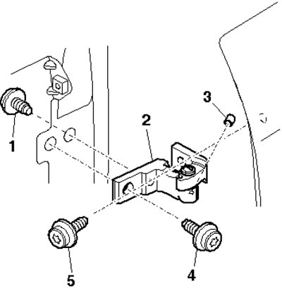
12. To adjust relative to the rear door, loosen the bolts (2 in the illustration) and move the striker so that the doors are flush with the adjacent body elements. Follow the marks (a and c in the illustration) for lateral adjustment and marks (b and d) for height adjustment. When adjusted correctly, the lock should fit onto the striker at the center. Tighten the striker mounting bolts to 25 Nm.
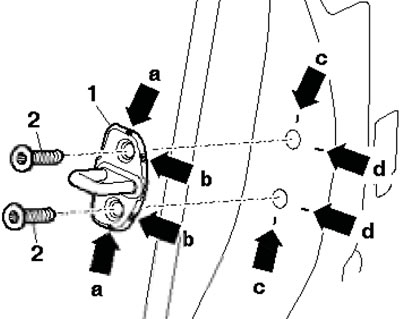
6.12. Adjusting the front door relative to the rear door
Door locking elements
13. The details of the installation of the door locking elements are shown in the illustration.
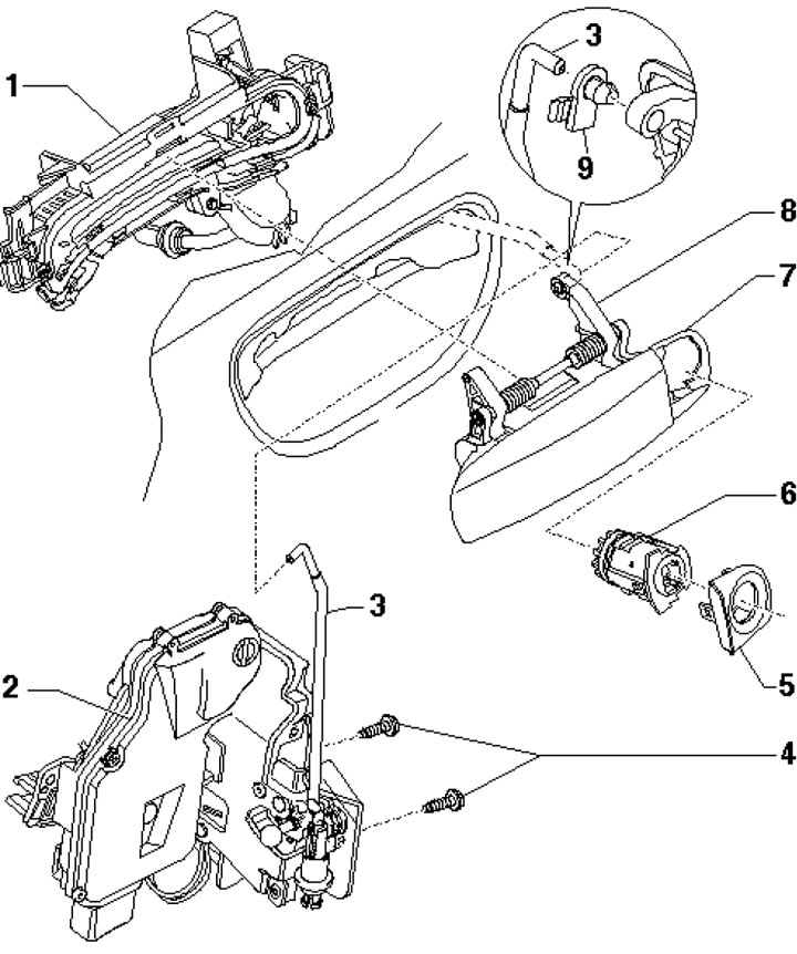
6.13. Front door locking elements installation details 1. Door handle support; 2. Door lock (to remove it you need to remove the frame and glass); 3. Control rod; 4. Bolt, 20 Nm; 5. Lock cylinder cover; 6. Lock cylinder; 7. Door handle; 8. Control lever; 9. Retainer
[The original article is posted on the resource: AUDImanual.ru]