



Table of contents: Removal, installation and adjusting… ↓ Lock and release handle ↓ Removal and installation hinges ↓
1. The installation details of the luggage compartment lid are shown in the illustration.
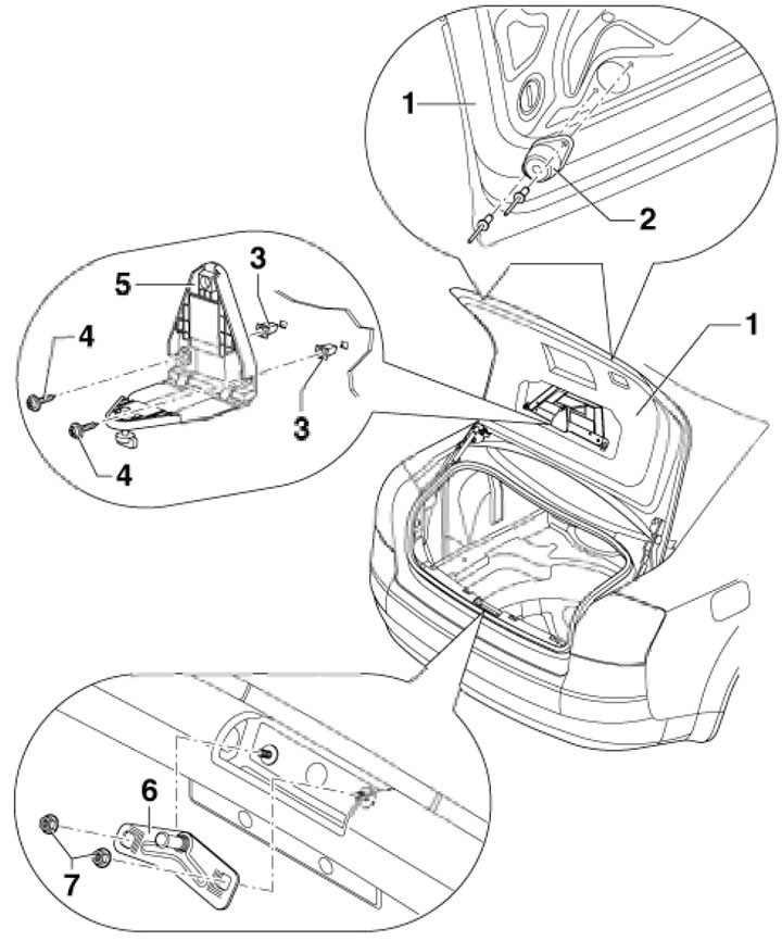 4.1. Trunk lid installation details 1. Trunk lid; 2. Stop buffer; 3. Expansion nut; 4. Bolt; 5. Holder; 6. Lock striker; 7. Nut, 8 Nm
Removal, installation and adjusting the cover
2. Remove the emergency stop triangle with the holder (5 in illustration 4.1).
3. Remove the trunk lid trim (see Part B), disconnect the connectors and pull them out of the cover.
4. Ask an assistant to hold the trunk lid, loosen the nuts securing both hinges to the lid and remove it.
5. Installation is carried out in the reverse order of dismantling the components.
6. To adjust, remove the cover and loosen the nuts slightly (1 in the illustration) lock striker mountings so that it can be moved. Carefully close the cover so that it is flush with the side body panels, then carefully open the cover and tighten the nuts to 8 Nm.
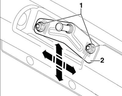
4.6. Adjusting the trunk lid
7. Remove the rubber cap, screw in the stop buffer and turn it out until the buffer rests lightly on the threshold (see illustration). Close the cap.
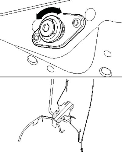
4.7. Buffer adjustment
Lock and release handle
8. The installation details of the lock and the trunk lid release handle are shown in the illustration.
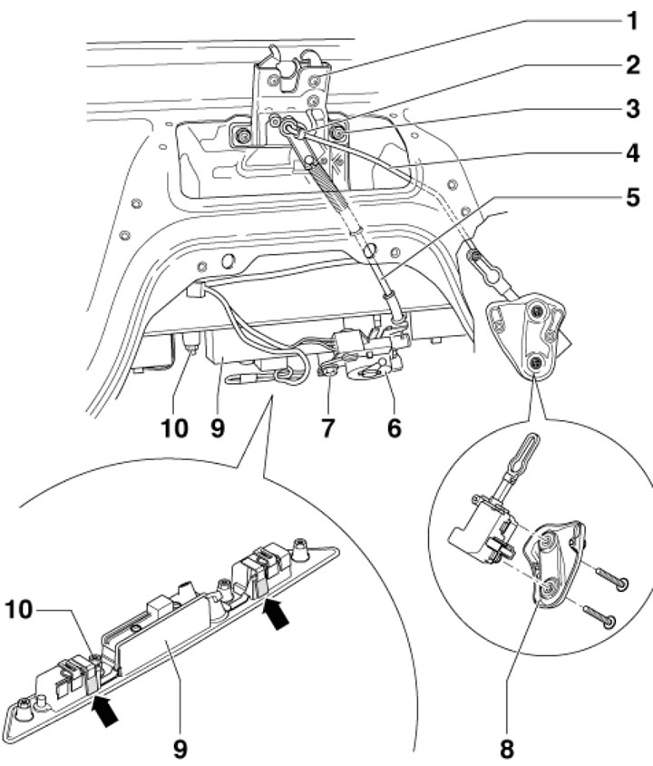
4.8. Details of installation of the lock and release handle of the luggage compartment lid 1. Castle; 2. Hinge bushing; 3. Nut, 8 Nm; 4. Control rod; 5. Bowden cable; 6. Lock cylinder; 7. Bolt with washer; 8. Electric motor; 9. Handle cover; 10. Nut, 8 Nm
9. To remove the lock, unhook the control rod from the hinge bushing and loosen the nuts (3).
10. To remove the lock cylinder, disconnect the connectors, disconnect the cable (6) from the lock cylinder, unscrew the bolt with washer (7), turn the cylinder a quarter of a turn and remove it from the handle mechanism.
11. To remove the handle cover, remove the lock cylinder and the luggage compartment lid trim. Loosen the nuts (10), press the locks (arrows) and remove the cover.
Removal and installation hinges
12. The details of the hinge and stand installation are shown in the illustration.
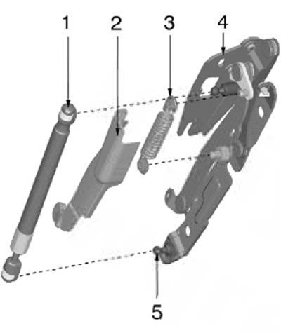
4.12. Details of the rack and hinge installation 1. Trunk lid pillar; 2. Spring lining; 3. Spring; 4. Loop; 5. Hinge
13. Give the nuts (1 and 2 in the illustration) and remove the trunk lid from its hinges.
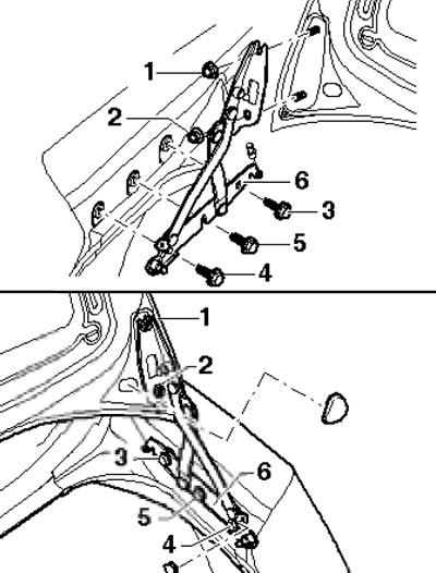
4.13. Fastening the hinge (eversion sequence)
14. Remove the bolts (3 and 4 in illustration 4. 13), loosen the bolt (5) and remove the loop (6).
15. Installation is performed in the reverse order of component dismantling. Tighten the fasteners with a force of 21 Nm.
(The original text is available on the website AUDIMANUAL.ru)